ELECTRICAL POST - LITHIUM !!!!
")
HI all
IT is time for a long overdue post on my progress.
Bear with me , LOOOONG POST WARNING
This is not a beginner post on LIFEPO4 ( lithium ) . If you want more info on lifepo4, go and lookup on
Technomadia, and the
https://marazuladventures.wordpress.com/about-us/Mar Azul Adventures (look for the PDF attachment at the bottom) which was my inspiration / guideline for designing my own system.
THE LITHIUM (LIFEPO4) SYSTEM has been built and tested and it's working now!!
IT has not been any easy endeavour, it was a very bumpy road , and i don't think it's a simple project to undertake, specially if you don't get an integrated system ( like smart battery or lithionics or mastervolt's lithium / victon's lithium , but they are pricey.)
I went on the route of custom LIFEPO4. system for the following reasons:
- I wanted to save money , vs an integrated system. In the long run, it saves you money. THe initial investment may be very similar to an integrated system.
- I wanted to be able to power an RV air conditioning solely on batteries. In theory,I implemented my system so i could run the AC and another major appliance like a space heater or a microwave. THis still needs to be tested.
- I wanted to be in total control and understand my system - this is to blame on the geek side of myself, but i know it'll pay off in the long run since i got to understand and know every component in my system. Moreover, if something breaks, i would be able to diagnose / fix / replace quickly.
- THe inverter / charger that i decided to go with, will be the victron 12v/3000 watt. it is a powerful inverter which will be able to power up my dream loads. I have not yet gotten the inverter, but it is still in my todo list.
- The end result is:I ended up with a sturdy monster that is capable of handling up to 500 AMP continous. I have tested the system, but with far less current ( 15 amps) , once I buy and connect the inverter, i will provide an update.
After all these design thoughts, i went ahead and bought a
12V 200AH 2.6KWh LiFePO4 system from Elite Power Solutions.It was $2,100 two years ago. It comes with cell balancers, which will balance the cells by applying a load of 1 ampere. The package included a shunt, an LCD screen, the Battery Management System (BMS). The BMS is very handy, and a MUST HAVE from my point of view if you go the route of LIFEPO4. The package also included a tiny 15AMP charger.
THe first thing i did was to read a lot and to build my diagram in microsoft VISIO. It is very worth to put time designing your diagram first. Once i got the design of the system I went ahead and started buying components.

The providers that i used were mainly amazon and genuinedealz, but also found gregsmarinesupply pretty cheap. The one that was too expensive is waytekwire, they even charged me a 'small order fee'.
Additionally, spent around 936 dollars on the rest of the compontents, the most expensive components were the BLUE SEA latching relay(BLue sea 7713, 190 on amazon) and a couple of massive BLue Sea 500Amp busbars, 75 each.
I decided to go with a latching relay because it has ver very little energy consumption, compared to a regular contactor. If i remember correctly, it consumes less than 10 mA according to my multimeter. THat is a significant power savings versus traditional relays/ contactors that consume 10 times more if not more (>140 mA) ,
Another design consideration: The Blue Sea 7713 has to consume some energy even when OFF. That wouldn't work for me, so i got a tiny relay (ELK912) that would cut the negative side of the 7713 to completely cut off the power consumption when OFF. The tiny relay consumes 30 mA, which is still kind of energy savvy compared to a traditional relay.
I designed the system so when there is an undervoltage event ( any cell is less than 2.7 or 2.8, my memory is bad), it disconnects everyhing from the system.
Also, i put an extra tiny relay (ELK912), so in case that it is charging from the victron and there is an overvoltage event ( any cell is greater than 3.8 Volts), it'll send a signal to the victron ( inverter / charger) .
At this point of time i have succesfully tested the system in the following ways:
- The cells came from the factory at around 50% charge ( 13.3V) ,and first i charged it all the way to 100%. I could see how the cell balancers started acting on some
cells when we were getting close to full. Then, the charger stopped charging ( it didnt trigger an over voltage because NO cell reached 3.8 V.)
- Then i put a load ( my new led bars that i got, but that's for another post), and discharged until i triggered the alarm of undervoltage. (any cell is less than 2.7
or 2.8, my memory is bad), which successfully trirggered an undervotage alarm event ( it changed from +12V to 0V on the ov output pin of the BMS)
- Then I recharged again, and the cycle was successfull!!!!!
YOu can see the monitor of the BMS very useful, showing the current load, the current voltage per cell and in the entire system, and the capacity. It is measuring all that through the shunt, so it is a reliable way to monitor loads.
This also monitors each cell's temperature:

 Physical IMplementation:
I wanted to utilize as little space as possible, so decided to create a 'Case' for the battery that will actually have attached all the elecrical components to it.
SInce it is a lithium battery, it won't offgas. No need to have it in an enclosure separate from the main living space.
The one disadvantage of my custom enclosure is of course poor ventilation of the battery. I am thinking of making several tiny holes ( 1 - 2 inches in diameter) on the 1/2 inch plywood case, in hopes to enchance ventilation to the battery. I hope those ventilations hole ( still to be made), will provide relief to the battery on summer temperatures, which are anyways harmful to my Lifepo4 battery.

At the very bottom of the fixture are the cell batteries ( 4). Then, once you connect the cell balancers (following the manufacturer's manual), you need to run cables along from one end to the other. ON top of all that, i made my plywood case making it a bit taller than the batteries, so that it doesn't crush the BMS' cables (underneath the plywood case).
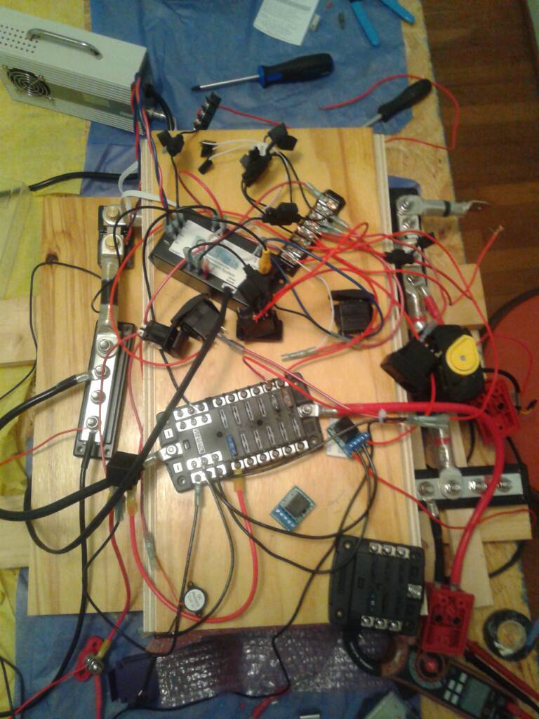
Then on top of the plywood case, you can see these components:

1. The bms, which is the heart of the entire system. Elite POwer solutions did a great job documenting this thing so i won't go through it again.
2. a blue sea 5026 fuse block, it's integrated negative bus comes very very handy, and it is there for the 12V loads. I anticipate connecting my fantastic fan, the led lights, a 12v fridge, and all my 12v loads, like ciggy chargers, etc.
3. a blue sea 5028 fuse block, this is always hot and its to turn on the entire system, also i connected the charger directly to this one , IT also can power up the BMS system / lcd without having to turn on the entire system . THis may come in handy for diagnosis/ failure / troubleshooting of the system in the future.
4. A terminal block in the center , for connections between all these devices.
5. A couple of small relays ( THe tiny blue ones, they are ELK 912 relays), one connects the negative pole of the 7713 latching relay, and the other one is to 'cascade' the two outputs (Over voltage and Under Voltage). THis is gonna come handy when the victron becomes the main source of charge. IN that case, either if there is an overvoltage or an undervoltage, the victron should be disconnected. Both ELK relays are driven by switches, one is directly on the battery since i dont anticipiate to use it heavily.
6. CLose to the rear, a car didode relay RC400112DN, this is to control the 'alternate' charging source (other than the inverter / charger), so far i have used it to control the charging. I have been charging my system with the included 15amp charger .But i decided to install this relay to possibly control other charging sources in the future ( perhaps solar??)
7. CLose to the front, you will see a looong strip of terminal blocks, which connect to the different switches of the system.
Next post will show a pic of the TOP already connected, and will continue explaining some of the components.