Thinking I am smarter than the engineers...Redpill me please.

Van Living Forum

Help Support Van Living Forum:

This site may earn a commission from merchant affiliate links, including eBay, Amazon, and others.
BradKW said:
#4 awg is big, no reason to use anything bigger than #8 I believe, and even that is probably overkill to the CC.

I disagree.  AWG 8 gauge will give a 7% voltage drop in a 10 ft run.  AWG 4 will give a 3% drop.  AWG 2 will be about 1% drop.  Solar gives such little power that one wants to capture as much as possible.  AWG 8 will work but IMO the power lost is not worth saving a couple of bucks.

The most problem resistant solution to combining 6 sets of leads into one is using ring terminals and a buss bar inside a waterproof box on the roof and running one pair of larger wires through the roof to the CC.

 -- Spiff
 
OP, you've got so much going on in one thread here, if not all your Qs get answered here, I would suggest breaking subtopics off later into new threads for more specific questions.
Optimistic Paranoid said:
mc4 connectors don't take wire bigger than 10 gauge
#8 is the biggest, but the specialized Rennstein crimper is expensive.

Maybe waterproof Anderson style?
 
Optimistic Paranoid said:
I'm not quite sure what you plan to do here.  AFAIK, mc4 connectors don't take wire bigger than 10 gauge,  so I'm not sure how you are going to hook them up to a 4 gauge wire.

The only way I can see to do what your diagram shows is to strip some insulation off the 4 gauge wire, wrap the bare wire from the panel around it, solder it and insulate it with tape.

Frankly, looks like a whole bunch of potential failure points compared to using a combiner box.

If I'm misunderstanding how you plan to do this, maybe you could explain it a little better.

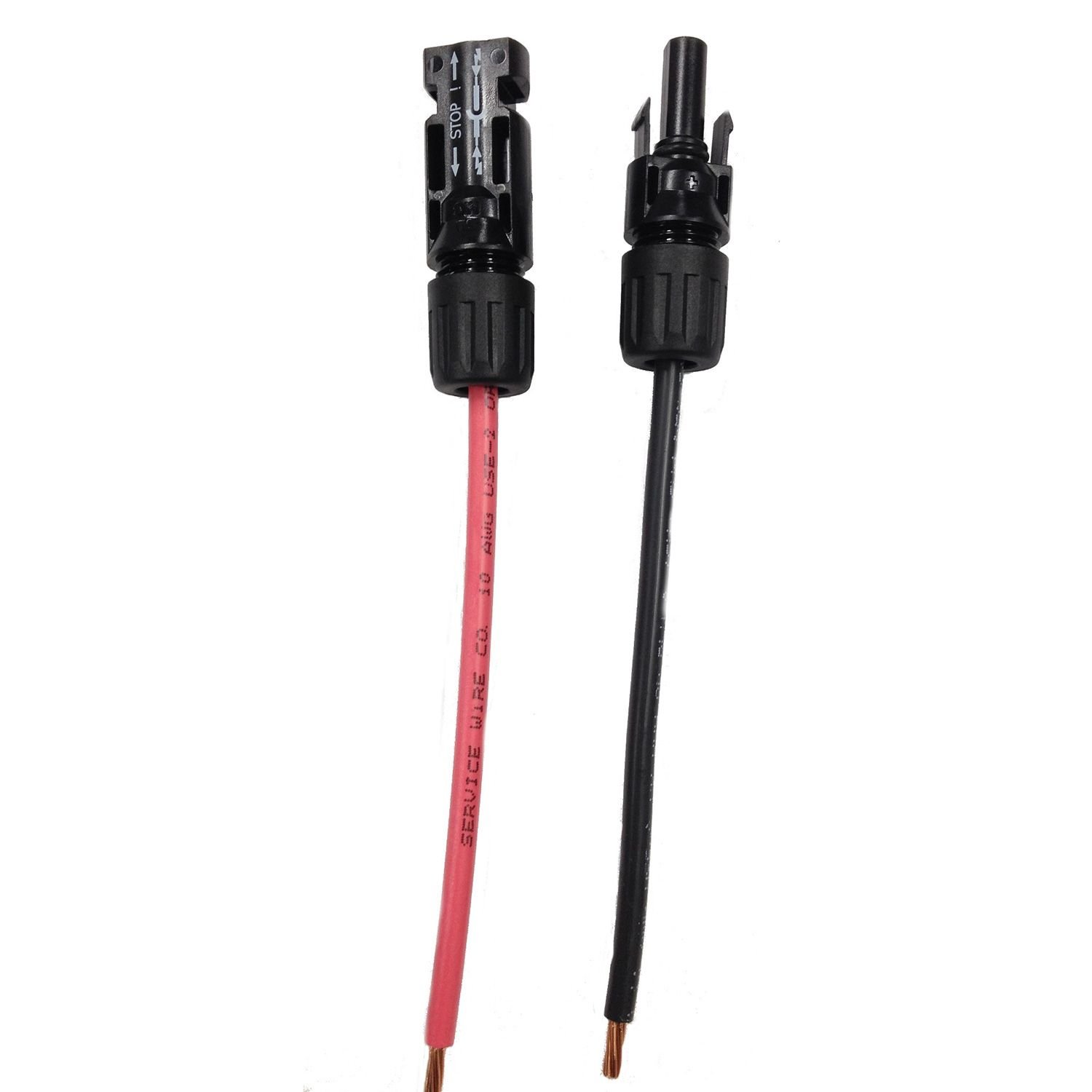
You are just about right there, But I was planning on using MC4 to bare connectors I make myself. I have 10 gauge wire and the MC4 connectors to spare. It would be something like this below that gets used to connect the solar panel's existing MC4 connectors to the two main #4 AWG cables. I would then, as you said, shave a bit of insulation off the mains, make a thick solder joint, and apply a new layer of insulation under a heat shrink wrap. This way, I do not need any extension cables for my panels to reach the combiner box or MC4 combiner connector things and I do away with those combiner items entirely by running the two leads straight to my charge controller. I also have other issues with a combiner box...It needs to be very low profile to fit on my roof in a stealthy way... I have yet to find one that is short enough to fit under my panels and roof rack. Additionally, I would need to purchase extension cables to rout the panel's outputs to the box, as their leads are about 18 inches long...AUGH! WHY SO SHORT!?

61ikjGaC8hL._SL1500_.jpg
 
BradKW said:
So your error here is thinking that your panels will produce 12v...they won't, they produce more like 18v, thus the 160 watt = 9 amps x 18v. Which puts ya over the 60 amps.

#4 awg is big, no reason to use anything bigger than #8 I believe, and even that is probably overkill to the CC.

Your diagram is fine, the problem comes in each of those branching connections needing to be weatherproof. It's doable using MC4 Y-branch connectors (is how I did it), but this is not the "easy way". Buying a MC4 crimper and learning the ins and outs of manufacturer variable MC4 fittings is much more effort than running to a combiner box. You'll need the box anyway (actually I used a Blue Seas puck) for water tight penetration through roof.

Sounds like you've got a fun build ahead, hope to start a build thread and keep us posted with pics   :)

Edit: OP is correct, #10 is max for the MC4 connectors I used...

Where do I find one of these crimpers and are they necessary? Also, why is the listed current on the panels so much lower than the theoretical current you describe here and why would the morningstar technical support people tell me the controller would handle my load, when I gave them the specs for my panel array before I bought the controller? Wouldn't the panels suffer some voltage drop over the wires to the controller, making the effective current output delivered to the controller smaller? Additionally, shouldnt the current output to the charge controller depend on the load the battery and inverter pull during charging?
 
Proper crimping is critical for low resistance, longevity and safety.

genuinedealz.com is the way to go if you don't want to go down that expensive rabbit hole yourself.

In fact if you do precise scale drawings, spec everything out, they might just design and make a full-on custom wiring harness for you, better than anything we'll come up with.

Worth asking them for advice and quotes anyway.
 
12v solar panels don't put out 12v, they put out 17-21v. the label on the back of your panels tell you the output voltage. highdesertranger
 
Spaceman Spiff said:
I disagree.  AWG 8 gauge will give a 7% voltage drop in a 10 ft run.  AWG 4 will give a 3% drop.  AWG 2 will be about 1% drop.  Solar gives such little power that one wants to capture as much as possible.  AWG 8 will work but IMO the power lost is not worth saving a couple of bucks.

 -- Spiff


I don't believe this is correct?

Here is a link to calculator I have used:  Voltage drop calculator

Parameters I put in: 10 awg over 10 feet carrying 18 volts @ 7 amps.

Results: Voltage drop: 0.14
Voltage drop percentage: 0.78%
Voltage at the end: 17.86

MichealT: I'm not sure what you are saying is different, as each calculation I've shown you uses the 160 watt number you gave for your panels. If, for example, we went with what you wanted it to be (panels output only 12v) then you would have 108 watt panels, not 160.  Quite possible the Morningstar tech didn't correctly process the number of panels you plan on using perhaps? hard to say, the numbers are the numbers.

But don't worry too much, I was in the same situation except I hadn't already purchased the TriStar 60 yet. The fact that I ended up with that controller anyway should give you confidence you haven't wasted money. Simplest solution from my perspective was going to a 24v battery bank and 24v inverter. You can easily then convert to 12v for things like lights and fan... or get even more complicated like I ended up doing   ;)

MC4 crimper isn't much, maybe $40? don't recall offhand. However, you'll need it to add MC4 connectors to build your wiring array...nothing else works. I did try. My comment about different manufacturers making MC4 that don't mate together is accurate though, and it added a very real frustration level and additional ordering   :/
 
BradKW said:
I don't believe this is correct?

Here is a link to calculator I have used:  Voltage drop calculator

Parameters I put in: 10 awg over 10 feet carrying 18 volts @ 7 amps.

Results: Voltage drop: 0.14
Voltage drop percentage: 0.78%
Voltage at the end: 17.86

MichealT: I'm not sure what you are saying is different, as each calculation I've shown you uses the 160 watt number you gave for your panels. If, for example, we went with what you wanted it to be (panels output only 12v) then you would have 108 watt panels, not 160.  Quite possible the Morningstar tech didn't correctly process the number of panels you plan on using perhaps? hard to say, the numbers are the numbers.

But don't worry too much, I was in the same situation except I hadn't already purchased the TriStar 60 yet. The fact that I ended up with that controller anyway should give you confidence you haven't wasted money. Simplest solution from my perspective was going to a 24v battery bank and 24v inverter. You can easily then convert to 12v for things like lights and fan... or get even more complicated like I ended up doing   ;)

MC4 crimper isn't much, maybe $40? don't recall offhand. However, you'll need it to add MC4 connectors to build your wiring array...nothing else works. I did try. My comment about different manufacturers making MC4 that don't mate together is accurate though, and it added a very real frustration level and additional ordering   :/
 

Attachments

  • IMG_20170607_193027.jpg
    IMG_20170607_193027.jpg
    465.4 KB
I think what you're not getting your head around yet, and believe me it took me awhile too, is that a CC converts ALL the energy being pumped into it. Amps AND Volts.

So look at it this way: What happens when solar input is 20 volts and the 12v battery bank only wants 14 volts? The CC converts the volts to amps if the battery will take it.

I'm going to link a Morningstar String calculator, I hope the data I choose will show in the link. I picked a random 150 watt panel, and even at that you can see that 6 panels drops into the Red zone of too high for the mppt 60: http://string-calculator.morningsta...x=15.5&tmin=0&tmax=30&tminunits=c&tmaxunits=c

Scroll down to the chart, 6 modules on 1 string...hover over chart numbers
 
BradKW said:
Here is a link to calculator I have used:  Voltage drop calculator

Parameters I put in: 10 awg over 10 feet carrying 18 volts @ 7 amps.

Results: Voltage drop: 0.14
Voltage drop percentage: 0.78%
Voltage at the end: 17.86

You are correct for one 160 watt panel.  Michael T has 6.  What I used:

6 X 160 = 960 watts ÷ 18 volts = 53.3 amps (rounded to 54)
Sticker on back of panel is showing 18.7? Vmpp and 8.62 Impp (per photo supplied in post #28) so max amps will be 51.72.

I show numbers for 2, 4, & 8 AWG, variable load, 105º rated wire, fuse terminated, 10 foot run (20 feet round trip) using  http://circuitwizard.bluesea.com/#
I get a similar numbers with your calculator.

I calculate 54 52 amps at standard conditions which is below the rated capacity of the TS 60.  You could cut the current in half by going with serial/paralled connecting for 24V to the CC, then running 12V or 24V, whichever makes most sense to you.  Most RV stuff is 12V, I have no experience with 24V stuff.

 -- Spiff
 
Aha, my apologies...that is indeed why I went with panels in series to avoid the drop. Forgot that detail.
 
BradKW said:
Aha, my apologies...that is indeed why I went with panels in series to avoid the drop. Forgot that detail.

Spiff hit the nail on the head, My solar array does 'just' fit into the operational envelope of my CC. 

However, no one has tackled my previous question yet, and that is regarding the safety of using two large leads to handle all the current and feed it back to the charge controller. I want to know if there are any traps lurking in that kind of wiring setup before I embark on setting up in my system. 

Thanks again to everyone who has participated thus far!

:D
 
how are you going to splice the panel wires into the two large leads? how are you going to waterproof them? how are you going to feed the wires through the roof? all this is solved with a combiner box that is why I recommended one. highdesertranger
 
highdesertranger said:
how are you going to splice the panel wires into the two large leads?  how are you going to waterproof them?  how are you going to feed the wires through the roof?   all this is solved with a combiner box that is why I recommended one.  highdesertranger

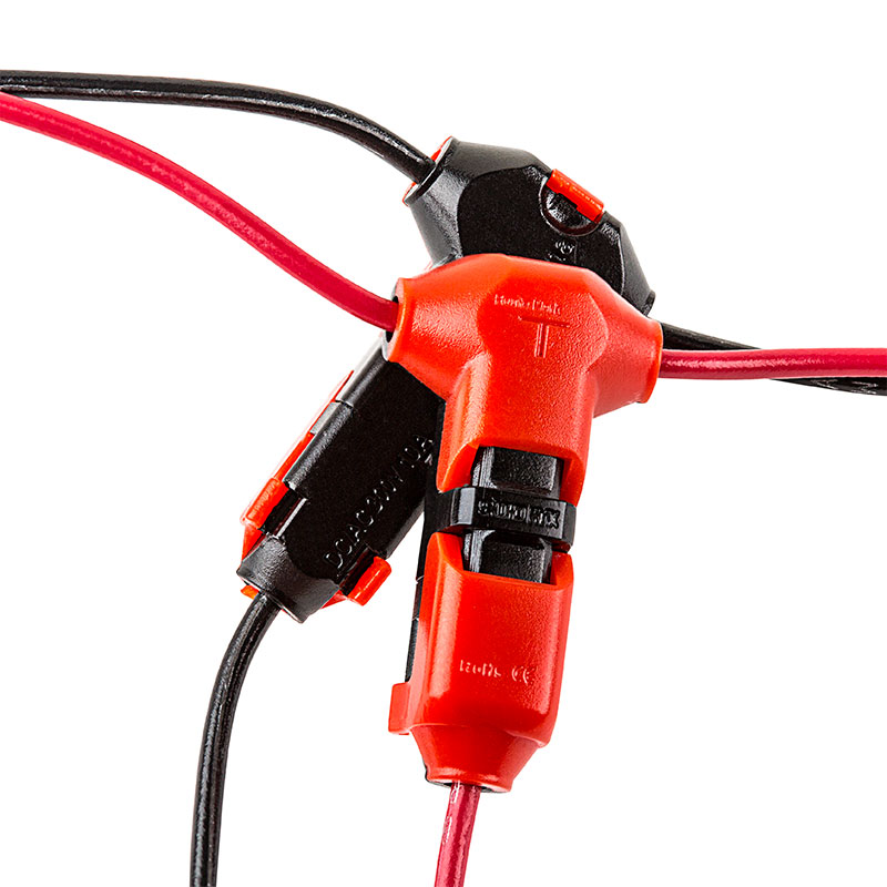
I was planning on using something like below...called a T- Tap connector I think, then heat shrink wrapping it with some outdoor nylon wrap, to connect the panels to the big #4awg mains via 6 pairs of MC4 to Bare Connectors.

As for running through the roof, I have a Solar Cable Gland already attached that will take #4 wire, plus I have rubber grommets in the holes I have drilled to keep the metal from wearing away the insulation on the wires... The gland acts to water proof the hole and acts as a cable stress relief. I understand that the combiner box will work, but where would one mount it inconspicuously, not so far from the panels that it needs a ton of extension cables, and also without having to cut additional holes in the roof?

I will upload pictures of the van tomorrow, perhaps in a thread titled for build logs or something....I will link it here once it is up. That way you all can see what I see and have a better idea of why I ask the questions I do. 
Thanks again for the help.
non-stripping-multi-connection-wire-connectors-power-wires.jpg
 
In a mission critical situation the single most important thing you want is redundancy. Pushing a single controller near it's upper limit is just the opposite of that. It would be far better to have two controllers--every element of the transmission of the power into the battery would have a great deal of stress taken off it. And when an inevitable failure occurs you're still in business and live to fight another day.

The only negative drawback (other than cost--but that isn't mission critical) is another gland through the roof and that is a tiny, minor drawback with unimportant consequences of failure.

Some amazing men have a saying, "Two is one, and one is none." I think they are right. I have 480 watts on my roof with 240 watts leading into two controllers. When one fails (and eventually one will) I'll still be good.
 
Michael T. said:
I was planning on using something like below...called a T- Tap connector I think, then heat shrink wrapping it with some outdoor nylon wrap, to connect the panels to the big #4awg mains via 6 pairs of MC4 to Bare Connectors.

Those are the cheap and lazy way to make connections.  I would guess that they have a big voltage drop across the connection.  As HDR said, a combiner box will give you the best connections with little chance of problems.

 -- Spiff
 
BradKW said:
At 960 watts, you're actually going to be exceeding even the TriStar 60's maximum input at 12v... 960/12 = 80 amps. Which means you've got a few choices:

Morningstar mppt controllers tolerate overpaneling well (current, not voltage); they describe the benefits/drawbacks in their own literature.  They do advise not overpaneling when at the extreme of the CC's ambient operating temp range.
 
Michael T. said:
Spiff hit the nail on the head, My solar array does 'just' fit into the operational envelope of my CC. 


Actually no, nothing changed on that front...series vs parallel lets you adjust how the current gets to the CC: 1) low amps + high voltage, or 2) high amps low voltage. Still the same overall wattage though.  By upping the voltage and lowering amps, you can get away with much smaller wire sizes without suffering voltage drop.

You still have the problem of your system being over-paneled by design with those components. Please follow the link to Morningstar's own String calculator that I gave in last post and work through understanding what it means.

Doesn't matter to me if you choose to overpanel that 60 amp controller or not, just understand what you are actually doing so you can make an informed choice...
 
I'd put just 5 of the 6 on that controller and get another smaller controller for #6 and keep your starter battery happy with it or connect it to to your main bank on cloudy days.
 

Latest posts

Top