highdesertranger
R.I.P HDR
- Joined
- Apr 4, 2012
- Messages
- 22,892
- Reaction score
- 92
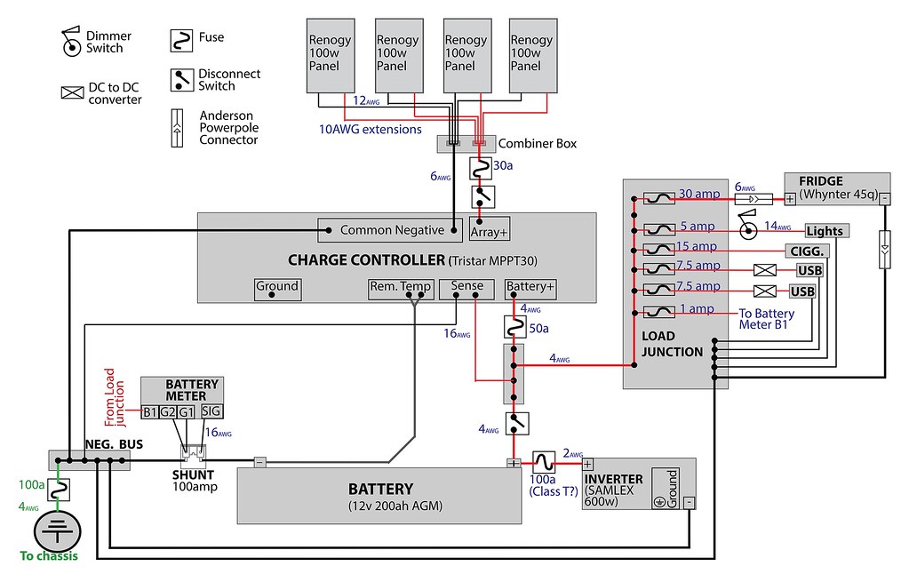
your controller should have a battery positive, and a battery negative. you have the battery positive marked but don't have a battery negative. I was thinking the terminal you have marked as ground was battery negative. if it is battery negative and you hooked it straight to your battery you would be talking the solar out of the loop and the meter would not read it. again I was told only one ground wire on the battery and this wire goes to the shunt all other grounds hook on the other side of the shunt. highdesertranger