Understanding bar

Van Living Forum

Help Support Van Living Forum:

This site may earn a commission from merchant affiliate links, including eBay, Amazon, and others.
If you're 2/0 from the Inverter bypasses the shunt and goes directly to battery ground, you won't be measuring the power the Inverter is drawing.
 
Yes negative for everything you want to measure must go through the shunt.
 
Well... I will have to get a couple of new cables now...
One to go to the left side of the shunt from the battery,
One to go from the right side of the shunt to the buss bar,
And maybe more....

OMAYGOODNESSSSS!!!!

Such Fun!!! (not?)
 
Again, nothing was mentioned about the various size cables in the ground systems... ?

Do I need to worry over that at all?

I mean, I have sizes from 2/0 down to 10AWG in there...
Does it all blow up when the random 10AWG melts?
I simply don't understand as far as how the different cables can all co-exist peacefully?
 
In addition,

The shunt is like 70 amp I think, and the inverter fuse is 150AMP?

So which will pop first? the shunt or the fuse?

I suggesting that the ground "RUN" goes from battery to shunt, shunt to bus. inverter to bus?
Yet the fuse is on the positive side.

In my mind the Run in reality goes from load to ground, even if it has to pass thru all of the other items in the circuit...
That is my very basic understanding of electrical circuits... IS that even close?
SO if an issue arises where something has to give, which goes first, is it based on path, or strength?

I'm thinking the weak link in the chain is the strongest the chain will ever be?
Is that wrong?
 
galladanb said:
Again, nothing was mentioned about the various size cables in the ground systems... ?

Do I need to worry over that at all?

I mean, I have sizes from 2/0 down to 10AWG in there...
Does it all blow up when the random 10AWG melts?
I simply don't understand as far as how the different cables can all co-exist peacefully?
Ground wires on each circuit need to be the same size - or bigger - as the hot wire.

Current flows from hot back to ground.  There's no way current from a 2/0 ground wire can flow back through a 10 gauge wire.
 
galladanb said:
In addition,

The shunt is like 70 amp I think, and the inverter fuse is 150AMP?

So which will pop first? the shunt or the fuse?
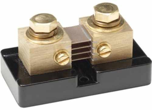
You need a bigger shunt.  The shunt must be sized to handle the maximum current that flows through it, which is basically all the current that is needed to run everything that will be running simultaneously.
 
OP says:
Ground wires on each circuit need to be the same size - or bigger - as the hot wire.
Current flows from hot back to ground.  There's no way current from a 2/0 ground wire can flow back through a 10 gauge wire.

That kinda makes sense... Each system will have the same size as the hot or positive, for each system...
But all the systems come together at the buss bar, so that's where I'm confused...

And OP also says...
You need a bigger shunt.

The one I have is what came with it. I guess I will have to look for a different meter?
It has a 100AMp shunt, not 70 like I posted earlier, sorry...
Here is the one I bought:
https://www.amazon.com/gp/product/B013PKYILS/ref=oh_aui_detailpage_o03_s01?ie=UTF8&psc=1
 
That meter, or one of the the reviewers says that meter only reads discharging current, and two meters would be required to monitor current IN and OUT of battery.


COnsider this option instead:

https://www.amazon.com/DROK-Multime...827988&sr=1-2&keywords=drok+battery+meter#Ask

I have no experience with that product, the link is not an endorsement of quality or accuracy.


If your inverter can pull more than 100 amps you might be SOL concerning a cheapo battery 'monitor'

My IPN pro remote uses a Deltec 500 amp  50MV shunt, most shunts on these cheaper meters are 75mv.  One cannot use a 50MV shunt on a 75mv meter

4160e58AAiL.jpg


My experience with an inexpensive 100 amp shunt and ammeter left me unimpressed as it could not be calibrated for both higher and low currents, and would not read currents less than 0.7 amps no matter what

[font=Verdana, Arial, sans-serif]So which will pop first? the shunt or the fuse?[/font]


[font=Verdana, Arial, sans-serif]copied from a amazon reviewer:[/font]
Note that most shunts cannot run at full current continuously.
[font=verdana, arial, helvetica, sans-serif]All shunts have a derating factor for continuous use, 66% being the most common. Continuous use is a run time of 2+ minutes, at which point the derating factor must be applied. There are thermal limits where a shunt will no longer operate correctly. At 80 °C thermal drift begins to occur, at 120 °C thermal drift is a significant problem where error, depending on the design of the shunt, can be several percent and at 140 °C the manganin alloy becomes permanently damaged due to annealing resulting in the resistance value drifting up or down.[/font]


[font=Verdana, Arial, sans-serif][size=small][font=verdana, arial, helvetica, sans-serif]Here is a 200 amp 75mv shunt, though I am not sure it will work properly on a 100 amp meter.[/font][/font][/size]

[font=Verdana, Arial, sans-serif][size=small][font=verdana, arial, helvetica, sans-serif]https://www.amazon.com/SMAKN-curren...9030&sr=1-2&keywords=75mv+shunt[/font][/SIZE][/font]
 
You need to get a shunt both large enough to handle all that current AND with the right mV spec for the monitoring device measuring off it.
 
And the higher the shunt's max capacity, as when trying to track a bank's SoC, the lower the resolution to measure small changes.

Bogart's Pentametric can track multiple shunts, so you could log the AH contribution from solar only, and/or the AH consumed over time by a fridge.
 
Today, installed a grounding pass-thru stud...

I used a wire brush to ensure a good bonding to the chassis and body.

This will allow me to get body to chassis grounds and will be accessible inside the van.

I had to make a grocery run, so I will check my work with a meter tomorrow!
And I have a 4 post buss bar coming Friday.
Hopefully, I will be able to order my last set of cables tomorrow as well

Getting there slowly for sure...

Such Fun! Right?

Here is where the 2/0 cable attaches to the chassis...
image.jpeg
 

Attachments

  • image.jpeg
    image.jpeg
    659.6 KB
Here is where the ground cable goes up thru the floor, looking up from the ground...

image.jpeg
 

Attachments

  • image.jpeg
    image.jpeg
    540.9 KB
Your ground cable to chassis should be against the chassis frame. Yours is restricted as the current must pass through the bracket holding the brake line. Can't you use the other hole I see in the frame? You just need a nut and bolt.
 
O, I see what your saying... I think the frame is all boxed in there, and I'm not sure if I can get a nut in there???

I have not hooked it up inside yet, so no biggie, YET?

Ill have another look down there...

Thx!!!
 
The Bolt/Stud/nut and washer are not supposed to carry any current.  The flat of the ring terminal is to be directly on the steel itself  for maximum surface area, with the bolt and nut and washer merely holding it to the steel.


Steel is a poor conductor.  There is no point in using 2/0 gauge if you are going to add so much resistance at the very end of the cable.

I'd also not trust the zip ties to last very long holding that much weight
 
SURE Wishing you were here. Maybe it would save us both time and me some money!

By the time I satisfy everybody, this van project will be the worlds finest, LOL!!!

And I didn't choose what material the chassis would be made out of, and I'm pretty certain it is the same as every
other chassis out there...

I mean shoot when you all say make the body ground to the chassis, is that not what I just did?
OK, sure, the actual location may not be perfect, but it was what was available at that moment....

I'm also not wanting to make swiss cheese out of the frame down there, so I was trying the best I could.
Which is why I used the zip ties. Used available holes, and that cable does not move very much anyway...
It's not likely to drop or become any more slack. It's just too fat and VERY stiff!!!

I'm not mad or angry, just trying to "Git-er-dun" and I welcome your onsite presence anytime your willing to drop by!
And I will accept any and all advice, hopefully in a constructive manner.

So PLEASE, instead of saying, "There is no point in using 2/0 gauge if you are going to add so much resistance at the very end of the cable."
Offer up how you would actually DO IT, like what do you suggest I do instead???? PLEASE?

As I said before, "I used a wire brush to ensure a good bonding to the chassis and body."
Meaning I made sure there is bare metal exposed under the bracket and the frame there...

I just mentioned I would look into moving the end over to the stand alone hole right there, near by, jeez...
 
Your pic indicates you attached the ring terminal on top of a nut, and perhaps a washer too. The flat of the ring terminal is to be in direct contact with the steel van floor. This way the current does not have to flow through the steel bolt and nut, which is/are poor conductors.

A silicon bronze bolt and nut would be much better if you wanted to use the fastener to conduct electricity rather than just hold ring terminal to steel. These might be available at Ace hardware.

I would remove fastener, place ring terminal flat against the van floor underside and use the bolt to hold it tight to floor underside. Then paint it with liquid electrical tape. On the interior I would also have the ring terminal in tight contact with the shiny floor, and the Nut and washer Only holding the ring terminal in place.

Yes this will likely require somebody under the van to hold bolt head in place, unless you get creative with some vice grips.

Do not use fasteners as electrical conductors. Use them to fasten only
 
OK, I now understand what your saying... I misunderstood your "steel sucs" comment as being what the chassis was / is made from...
I totally missed that you were talking about the stud going thru the floor!!!!
I THOUGHT YOU WERE YELLING AT ME FOR THE BOLT THRU THE BRACKET...

PLEASE, PLEASE forgive me...

Yes, I will try to correct that as soon as I can...

Just FYI, I used nuts on both sides of the floor so that I could access easily.
I could just as easily change it to a bolt and accomplish the same thing.

THANK YOU FOR BRINGING THIS UP IN AN EASIER TO UNDERSTAND IDEA FORMAT
FOR ALL OF US THAT NEED TO HAVE IT DRAWN WITH CRAYONS!!!
 
You most likely have your chassis ground just by bolting cable to the floor. But lose the washers between the cable and the steel floor. The cable from the floor to the frame is gravy, not a bad thing. But the cable end needs to be directly against the steel frame, not that bracket. The order would be something like (bolt)-(washer)-(cable end)-(steel floor or frame)-(cable end)-(washer)-(nut). And yes, using a nut on each end of a stud would be just as good as a bolt and nut combo.
 

Latest posts

Top