Please Help Review My Wiring Diagram

Van Living Forum

Help Support Van Living Forum:

This site may earn a commission from merchant affiliate links, including eBay, Amazon, and others.

nberna19

Member
Joined
Feb 21, 2019
Messages
9
Reaction score
0
Hi All,

First time setting up electric and complete noob at doing so, please keep patience in mind. I am trying to set up solar and electric in my van build out and have come up with the attached photo as my first draft of a wiring diagram. I was hoping to get some feedback and suggestions on it. A couple questions in advance:

[font=Helvetica, Arial, sans-serif]-Coming of my leisure battery I have 4 wires coming off of the negative terminal and 3 coming off of the positive terminal (I may also add an alternator charger in the future which would add 2 more wires). Is this too much coming off the terminals and should I consider wiring it all to a positive and negative busbar beforehand?[/font]
[font=Helvetica, Arial, sans-serif]-Coming off of the leisure battery, do fuses go before or after an on/off switch?[/font]
[font=Helvetica, Arial, sans-serif]-I'm not entirely sure of the correct fuses and gauge wire to use on each connection so please look out for this.[/font]

[font=Helvetica, Arial, sans-serif]Thanks for any and all help, Nick.[/font]
 

Attachments

  • IMAG0584 (2).jpg
    IMAG0584 (2).jpg
    1.6 MB
I think you know but I only see the one cable coming from each solar panel. Each panel positive and a negative wire correct? I would think that would be one place I would use a bus bar. The fewer connections the better in my opinion (which I am by far no expert) and I would use high quality military type cable ends on the battery. Fuses are used protect the wire I have been told in order to prevent danger of fire in 12DC systems so well insulated correct or even larger than needed gauge wires to me supply extra security but can be hard to work with so just to make things neater and easier to work with I sometimes use bus bars, just my opinion.
 
Wire panels in series if your controller will handle the voltage. Series is more efficient when using an MPPT controller.

Replace the 40 amp fuse from your panels with a switch. Your panels will never produce enough current to blow the fuse.

Move the fuse box connection from the controller to the battery side of the switch going to the inverter.

Fuses should go close to the batteries, so move the inverter fuse to the battery side of the switch.

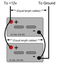
It's best to connect batteries in a balanced configuration. Either move the negative or positive wiring from the lower battery to the upper battery.

CvfzlzZ.jpg
 
It might be good, to place the fuses, on the wires going to plus of the battery, as close to the battery as possible.
This practice will help the fuse protect as many connections and as much of the wires as possible.
 
x2 on the military terminals, bus bars, and wire the batteries like diagram Tom posted. move the 12v fuse box over to the batteries don't run it off the charge controller. highdesertranger
 
[font=Helvetica, Arial, sans-serif]Thanks for all the feedback everyone. I attached an updated diagram w/ a couple changes to note. The solar panels are wired in series, I have the charge controller, 12v fuse box, and inverter connected to positive and negative bus bars before the batteries, and I added several breakers with on/off toggles. The batteries are still wired in parallel. Let me know what you think. Thanks again![/font]
 

Attachments

  • IMAG0585 (2).jpg
    IMAG0585 (2).jpg
    1.3 MB
here's what I would change.  notice my lame attempt to erase your negative wire from the buss bar to the battery and then reroute it to the other battery. this assures that the charge and load are distributed between both batteries.  the way you have it the one battery is going to take the majority of the charge and discharge.


IMAG0585 (2).2.jpg

highdesertranger
 

Attachments

  • IMAG0585 (2).2.jpg
    IMAG0585 (2).2.jpg
    1.6 MB
Thanks @highdesertstranger. I believe that's what @tom_m was alluding to with his battery diagram he posted. The 2 batteries should be connected positive to positive with battery A going to the positive bus bar; while also the 2 batteries should be connected negative to negative with battery B going to the negative bus bar. Correct?
 
Thank you for the clarification. What about my battery to battery wire size, inverter to battery wire size, and battery to bus bars wire size? Should those all just be 2/0 AWG? Also, I'm not sure about the 175A fuse I have running from the inverter to pos bus bar. Is 175 too large there?
 
nberna19 said:
Thank you for the clarification. What about my battery to battery wire size, inverter to battery wire size, and battery to bus bars wire size? Should those all just be 2/0 AWG? Also, I'm not sure about the 175A fuse I have running from the inverter to pos bus bar. Is 175 too large there?

I'm no expert on fuses or wire gauges. But 12VX175A=2100 watts. Does your inverter peak up to 2000 watts? Or is 1000 watts its peak output? Also doesnt your inverter have replaceable blade fuses?
 
You fuse for the size of the cable, not the load. You size the cable for the load it will carry over a fixed distance, in this case the inverter. There are many fuse to wire charts out there, here is just one: https://www.oznium.com/blog/how-to-determine-the-fuse-wire-size-for-your-project/

You can put in a smaller fuse than the wire will carry but run the risk of adding resistance to the circuit inducing voltage drop.
 

Latest posts

Top