Please give input on my electrical system design

Van Living Forum

Help Support Van Living Forum:

This site may earn a commission from merchant affiliate links, including eBay, Amazon, and others.

FALCON

Well-known member
Joined
Mar 28, 2015
Messages
500
Reaction score
0
Hello! I’m designing and electrical system for my van and I could use some feedback and advice. I want to do things right the first time and make sure I’m building a system that is safe and will work well. I knew very little about electric systems when I started this, and I am still not sure that I have things correct. I'd greatly appreciate any feedback you have.


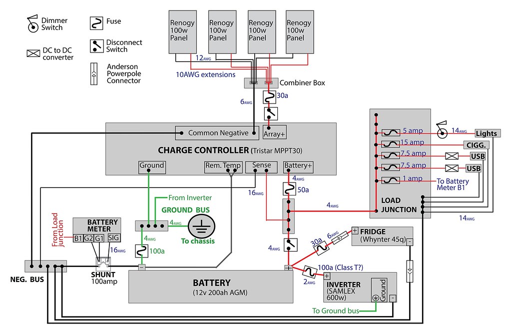
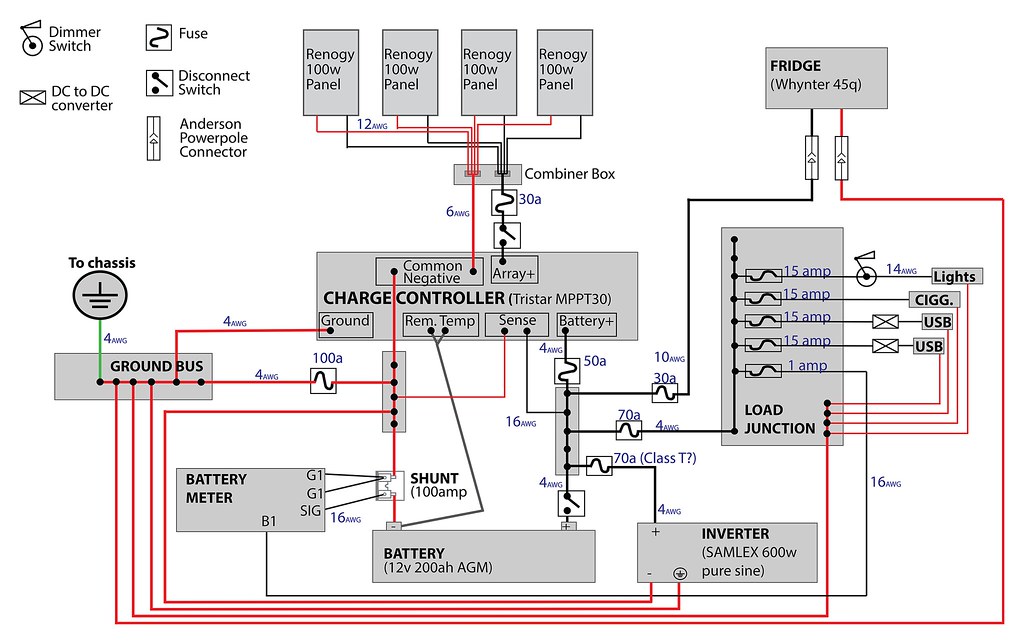
Here is the wiring diagram. I hope I’ve laid it out in a way that isn’t too hard to interpret.
23698244536_02c7c03867_b.jpg


Link to full size version (2600x1650pixels)  


Here are the questions that I have:
  • How does it look overall? Are things in the right place? What do I have wrong?
  • Am I missing any important equipment?
  • Do I need a ground fault protection device in the ground circuit? (more detail in notes below)
  • Do the wire sizes and fuse sizes look reasonable? (If a wire size is not shown for a negative cable, it’s the same size as the positive one)


Overall system details:


Some other notes:
  • I still need to figure out the details for the load outlets after the load junction, so I don’t show detail for those. I’d like to use DC-DC converters so I can charge most of my devices that have AC-DC converter bricks without needing to use the inverter and then convert back to DC.
  • There’s a good chance that in the future I will add a cable and solenoid to charge from the alternator. This is not in the design now
  • I’ve tried researching ground fault protection but haven’t been able to make sense of it yet. My CC manual says “This unit is not provided with a GFDI device. This charge controller must be used with an external GFDI device as required by NEC article 690” and… “The electrical system  negative should be bonded through a GFPD to earth ground at one (and only one) location”. I did look at article 690 but couldn’t make much sense of it, as it seems to be written with AC in mind(?)
 
Falcon:

Nice diagram!

I will look it over carefully; first cut I would make the +positive feeds red and the -negative feeds black; this is the normal configuration.

I have posted a similar diagram under "two questions" in the electrical section. I have an FET battery isolator in my system which you might want to investigate.

Thanks,
 
AFAIK, 12v systems are all black wires for ground and red wires for positive.  110v systems use black for the hot wire.  My brain is going into overload on the reversed colors. :huh:

You are connecting only in a mobile environment, no earth ground, no GFCI.

Your 12v grounds should be connected all together through the shunt and at the controller terminal 16 as far as I can tell.  Chassis ground to one of the lugs and battery ground to the other lug on the shunt.  You show two different ground buses with a fuse between them.  Wire as above.  Terminal 9 should not be connected to anything, this is for earth ground when installed in a S&B.

This is about as far as my pea brain can take it :p
 
I don't have a separate common negative and ground. I just ground everything to the chassis. You could create some ground fault situations if the ground fuse blows and you don't realize it. It's definitely possible to trip a 100 amp fuse if the inverter, fridge, and something else kick in at the same time.

You might be able to simplify a couple of things. For example you have a fuse between the battery and the fuse box. I'd just keep them close together and drop the big fuse. Also, you are running the fridge off a separate line with an individual fuse - I'd just wire it to the fuse box to keep it all in one place.
 
If you have room for two 66x39 inch panels you might consider going with two grid tie panels.  My local electrical distributor has the SolarWorld mono 285w panels for $270 each.  That is 570w of USA made panels for $540!  More power for less $.  I would spend a bit more and get the 60a Tristar controller.  The 60a version has Ethernet computer connectivity, a plus for sure, and would also allow you to add another panel later.  Or a bunch more panels later if you upgraded to a 24v system.

No doubt that 400w would be nice, 570w of solar would charge that AGM battery up much faster.  The faster that you put bulk current back into an AGM battery, the better it will perform and the longer it will last.  Flooded golf cart batteries are less picky on how they are treated.  Two hundred Ah of AGM is going to cost around $600.

Since you said "do things right the first time" I'm going to assume a learning curve will be involved as far as treating the battery bank in an optimum manner.  So I suggest that you consider buying a pair of the East Penn golf cart 6v batteries (duracell branded) for $110 each from Batteries + as learners.  Just be sure that they are fresh and have at least 6.3v.  They buy the golf cart batts by the pallet so a pair from the bottom of the pallet are likely be a bit older than those off the top...
 
Figures I would mess up the simplest thing possible and use the wrong wire colors!

Thanks for the input so far guys.

I was already wondering if I could just use one bus bar for the negative/ground side instead of the two of them. I sort of thought that having the fuse before the ground bus required having two of them, so thanks for clearing that up guys. I'm going to fix the colors and make changes to the negative/ground wiring.

I was wiring the fridge and inverter straight from the positive bus because I didn't want to use MAXI (blade / automotive) type fuses for them as I've read that those fuses are supposedly not sufficient for a system of my size (I'm not sure why they supposedly aren't. It's something I read in a textbook). If I remember correctly, the fridge and inverter manuals say to wire directly to the battery. Again, I'm not exactly sure why - I assume it has something to do with possible efficiency loss from multiple wire runs or more chances of connection failures. Anyone have further opinions on this? I would like to make things as simple as possible, while still ensuring everything works well.  

Also, I've already purchased most of the main components (The panels, combiner box, charge controller, inverter, battery monitor, and load/fuse junction box)
 
Some RVs use black for positive and white for negative on the 12v system just to add confusion and make mistakes easier. Always check if there is any doubt.
 
The fridge's are sensitive to voltage drop on their cabling. Many/most have low voltage protections to save the battery from over depletion and these can be triggered well before the battery is actually in danger of over depletion, if the wiring to the fridge is too long and too thin.

Sharing power busses with multiple items can cause issues if they are all running the same time, and there are some worries about transient voltage spikes when some items are turned off. The battery itself is a big electrical filter so it is often recommended items be wired directly to its terminals, but doing so is not always feasible or desirable.

The Ciggy plugs and receptacles are poor electrical connectors. When provided with compressor fridges, their wiring is too thin and too long from receptacle to fridge. Add in the wiring from battery to receptacle and the issues compound. Danfoss compressors that have too much voltage drop on their wiring, will activate the compressor fan still, and make it sound like the fridge is running properly, but the compressor is not actually running, only the fan.

Fuses are usually on the (+), not the (-)

In your diagram you have both cables from your inverter going to the (-) buss bar.

Cables from the inverter to battery really should not share busses with other devices, but be short and thick and wired directly to the battery terminals fused to protect the wiring used,.

A problem with Maxifuses is the fuse holder itself, less so the fuses, but there are a lot of very poor quality chinese junk that is all too easy to click place order upon, because Bussman fuses are significantly pricier.

There is a beautiful Maxifuse holder by Blueseas products that i drool over:

https://www.bluesea.com/products/5006/MAXI_Fuse_Block_-_30_to_80A

Its connecting/mating surfaces are large and can be done well with low resistance, rather than the lesser Maxifuse holders which use some sliding quick connects to grasp the tangs and can wear out or simply not exert enough pressure over their limited surface area.

Really the fuses/fuseholders should not be purchased on price. Pay extra for quality of a well respected brand name such as Bussman or Blueseas. There are many junky fuses and holders out there which will not open the circuit when they should. I had a 20 amp chinese ATO/ATC fuse blow at 3 amps, and had a 15 amp fuse not blow passing 20 amps, though the fuseholder melted, and I took the entire batch of econo fuses and smashed them with a hammer, so they would not get into my spare fuse bin.
 
[font=Verdana, Arial, sans-serif]There is a beautiful Maxifuse holder by Blueseas products that i drool over:[/font]

[font=Verdana, Arial, sans-serif]https://www.bluesea.com/products/5006/MA..._30_to_80A[/font]

SternWake, I use one of these as input to my fuse box.  I somehow screwed up the first one by tightening the screws without a fuse when i was checking it out.

I loosened the screws but the fuse was hard to get in and would never come out again.  The marine store swapped it out for a new  one and a new fuse.

The new one works great.  Just don't turn the screws until the fuse is in.  It was my bad but who knew.
 
good advice so far the one thing I would add is the fuses for USB plugs are to high imo. I would cut them back to 7.5A fuses. btw nice schematic just change your color coding. highdesertranger
 
Helpful thread...I'm still learning too. Please post updated diagram when you finish it :)
 
THANK YOU VERY MUCH FOR YOUR HELP!!!


I updated my wiring diagram. Here's a small version for this thread:    
23745789312_4803dab492_b.jpg


(HERE IS A LINK TO LARGE VERSION THAT YOU CAN SEE BETTER)


Some questions I have right now:

1 - Is my negative and ground wiring correct? Is the fuse in the right place? (or should the fuse be between the ground bus bar and where it connects to the chassis, so that all ground wires go through that fuse? If I remember correctly, the reason for the fuse is related to the battery, so that's why I left it near the battery)

2 - Does my positive wiring look ok? Is it actually feasible to wire three things to the battery positive terminal like I have shown?

3 - Should I put a disconnect switch on the cable going to the inverter? (I probably won't do so on the fridge because I could disconnect the Anderson Powerpoles I'll be using or simply unplug the wires from the fridge)

4 - If I wire the fridge and inverter directly to the positive battery terminal, do I also need to wire their negative cables directly to the battery negative terminal? Or is it ok to wire them to a bus bar?


B and C said:
Your 12v grounds should be connected all together through the shunt and at the controller terminal 16 as far as I can tell.  Chassis ground to one of the lugs and battery ground to the other lug on the shunt.  You show two different ground buses with a fuse between them.  Wire as above.  Terminal 9 should not be connected to anything, this is for earth ground when installed in a S&B.

I believe I got some other feedback also related to this. It took me a while to think I've understood what you wrote here, but I think I got it now. Please have a look at my negative and ground cables. Does it look like I have it right now? (But I also got feedback like Reducto's - to just use one negative/ground bus? I probably wouldn't have that separate ground bus bar if it weren't for the Charge Controller and Inverter having separate ground outlets on the devices. I'm not sure what to do here...  

I also made some changes to the positive wiring. I wired the inverter and fridge directly to the battery. I think both the manuals for these say to do this. Someone else said that wiring multiple loads to the positive bus bar would cause some problems. One concern I have now is that the disconnect switch on the cable to the positive bus will no longer disconnect the fridge or inverter. The fridge should be no problem because I could disconnect one of the powerpoles or just unplug the wires from the fridge. But maybe I should put a disconnect on the inverter line??
 
Ok and I just remembered something about the fridge - it comes with cigarrete lighter plugs on the DC cords, so of course it isn't supposed to be wired directly to the battery. I will move it to be wired through the load junction.
 
Get rid of the green wires/connections all together.  Those connections are for earth ground, not battery ground and are not needed in a mobile environment.

Really nice diagram :cool:
 
the only issue I see is the only negative to the battery should come from the shunt. every ground that bypasses the shunt will bypass the battery meter giving you false readings. at least that's how it was explained to me. somebody with more experience with shunts might give you better info. highdesertranger
 
Great diagram Falcon! I think I will use it :D

Could you explain what the difference between a shunt and a bus is?

TY!
 
highdesertranger said:
the only issue I see is the only negative to the battery should come from the shunt.  every ground that bypasses the shunt will bypass the battery meter giving you false readings.  at least that's how it was explained to me.  somebody with more experience with shunts might give you better info. highdesertranger
All the grounds are connected to the shunt and the shunt is connected to the battery negative as drawn.  Everything I see is wired just like mine except fot the green earth ground stuff.  Those connections are for use in a S&B where there is a 110v system in place and the earth ground is then required.  Trying to use it in a mobile environment might get you into a ground loop situation depending on the internal wiring of the connected devices.
 
Do you mean absolutely no grounding to the frame at all, like this?
23748878572_d53519aa52_k.jpg


Or, still ground the battery to the frame, like this?
23489330939_ff22b9bb89_k.jpg
 
FALCON said:
Do you mean absolutely no grounding to the frame at all, like this?
23748878572_d53519aa52_k.jpg

Yes and no.  Your negative bus should be the frame ground.  Your battery is then grounded to the frame through the shunt.  That way anything tied in and using a ground, the shunt will see and register it.  Everything else is correct.  This is the way mine is wired and works great.
 

Latest posts

Top