Help with continuous duty solenoid installation

Van Living Forum

Help Support Van Living Forum:

This site may earn a commission from merchant affiliate links, including eBay, Amazon, and others.

TooManyDogs

Well-known member
Joined
Nov 7, 2015
Messages
164
Reaction score
0
Hi all!

So, the van is still at the shop. The alternator rebuild was a bust (after reinstallation, I took the van to Oreilly and the diodes failed). My friend will take it back to the rebuild place and gave them fix it.

In the meanwhile, I watched Bob's CDS video and decided to trace the wires that powered the (removed) wheelchair lift back from the start battery.

3 wires come off the (+) post of the battery:
1) to power the van as usual
2) the wheelchair lift wire. Connects to a circuit breaker, then run through the engine compartment and under the van, up a hole to the back of the van. 2 other wires go up that hole, I'm assuming they're grounds.
3) ? with a 60amp fuse, through the engine compartment and then I lost it.

I want to install a CDS in the van and am going to replace that circuit breaker with a CDS and stall a bunch of fuses inline.

My questions are:
1) Wire 3: What could this be for? Could it be the switch in the dash of the van? How do I find out? Is there a trick to following wires under the van? Will this affect the CDS?
ed5b36c52bc014dd0036281241fea1d9.jpg
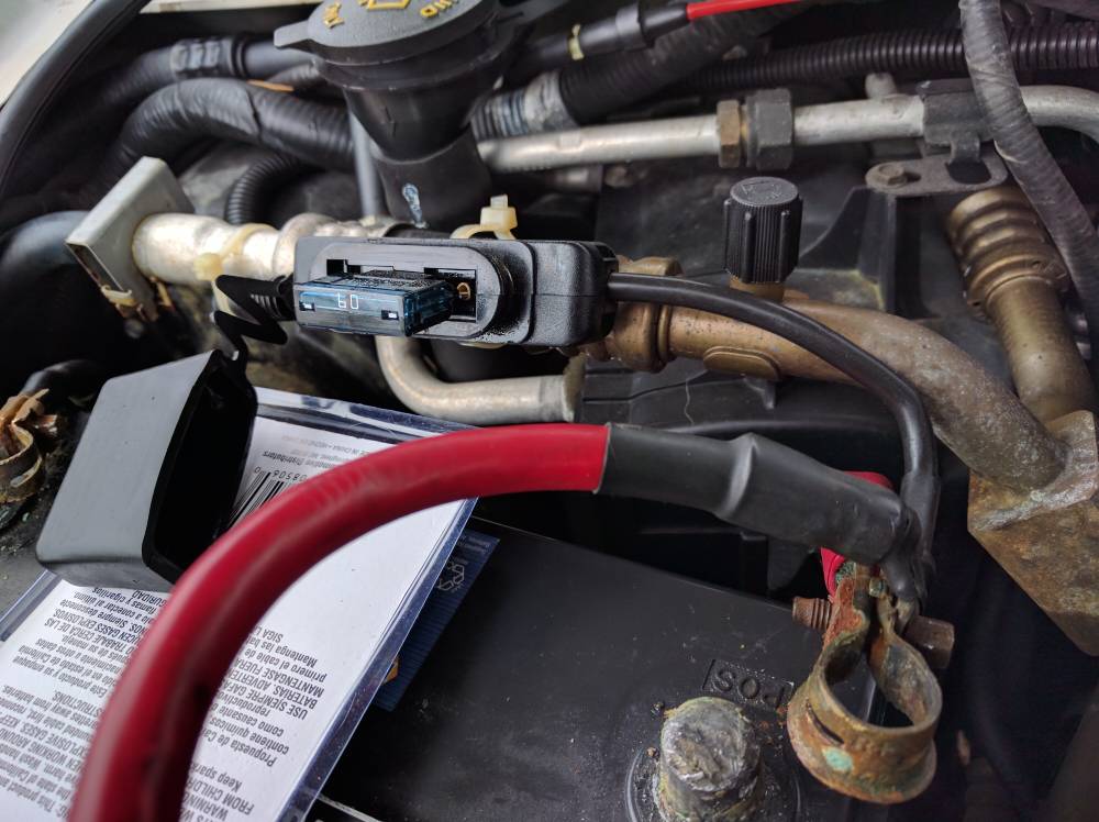
(As you can see, the battery is disconnected and my friend is going to replace the terminals.)
2) How to find a "live when key is turned on circuit" on the power distribution box under the hood. Do I stick the (+) end of the multimeter in the hole and the (-) on the frame? Is it better to find a relay slot or a fuse slot? Does it matter?
3) I found a diagram of the relays of the van. I have a relay in position E (trailer battery charge relay). I don't have a trailer or a battery. Can I unplug this to test the slot? Probably a bad idea, right? (The reason I'm asking about this one is that's the slot in the video that they wired into to energize the CDS. How consistent was Ford with regards to fuse/relay positions inside the box?)
4) Random question: what is this that's on the side of the power distribution box. The plastic cover is labeled "ALT" and "+".
5f49692db2e8538f4ee35c918db8e7dd.jpg


Thanks for your help. I feel like I'm everywhere and have so many seemingly random questions because I'm not really sure what anything is. I'm just guessing.
 
The 60 amp maxi fuse is likely something the previous owner added, perhaps as a way to run a smaller inverter that could not be run from a 12v ciggy receptacle? Not Familiar with Ford but it looks aftermarket, so you will need to figure out what it is to.

Pull the fuse and see if something no longer works. Put your head under the dashboard and see if the PO decided to leave some 8awg wires dangling that previously went to an inverter they decided to keep.

Diodes in alternators blow, when the alternator is producing a good amount of current, and then the circuit is severed. This can happen when someone decided to 'test' the alternator by pulling the (+) cable from the battery while the engine is running. It might not blow the diodes if the alternator was not making lots of current at the time the cable was pulled.
This 'test' can also blow other electronics as DC voltages can briefly spike well into the hundreds. It is unfortunate that this 'test' is still considered valid and will be referred to on all sorts of automotive related forums as a valid procedure to check alternator function on modern vehicles, when the test itself can cause the failure of the alternator.

Make sure the battery to engine ground wire is tight/clean/ has no corrosion wicking under the insulation.

How to find an appropriate trigger circuit for the solenoid? Well, Ideally one would choose a circuit that becomes live only after engine starts. I know on Dodges the Hvac blower motor circuit is deactivated during engine cranking, but is live with key to on. not start, So effectively the solenoid engages when the key is turned to on, hooking the batteries together, then disengaged during cranking, then engaged after starter motor does its job and the key is then released. This is 2 cycles of the solenoid, and will wear it out faster. Not ideal, but it works.

Some other circuits will engage with Key to on, and during starting, so the house battery will assist the engine battery. Again, not ideal, but it works. The solenoid passing starter current will also wear the contacts within faster, and any delicate electronics hooked to house battery, say for the 12vDC compressor fridge, might not be very happy with the voltage spike backfeeding when the starter motor is disengaged. This damage could be cumulative over a period of time, or perhaps never be a factor.

Not being familiar with Ford, i hesitate to recommend this, but my Dodge had an 16awg unused connector dangling under the dash that becomes live only after engine starts. I utilized this for my aftermarket voltage regulator but it would be ideal for triggering a CDsolenoid, if I used one.

One can always tap an unideal trigger circuit, or even just 12v anywhere, and use an illuminated switch to control when the solenoid is allowed to engage or disengage. This has an additional advantage when battery is very depleted and alternator belt is wet and slipping and squealing.

The ALT + box is most likely the OEM fuse for in between alternator and starter battery. Does not look like any fuse I am familiar with though.

I would recommend taking power for Solenoid to house battery from alt(+) stud instead of engine battery, to bypass this fuse and the whole OEM charging circuit which will act as an electrical bottleneck when house battery is depleted.
 
SW wrote, *I would recommend taking power for Solenoid to house battery from alt(+) stud instead of engine battery, to bypass this fuse and the whole OEM charging circuit which will act as an electrical bottleneck when house battery is depleted.*

Worked for me.
 
OP-I do have a Ford. It's a 2004 e350. Thanks for the link!

SW-Thanks for the info. So it looks like the Alt (+) box does contain a 175 amp fuse, connecting the alternator to the battery, as you said! I will work on the 60amp maxifuse as the weather warms up. Thanks!

Is there a trick to removing the doghouse? (I know about the 3 latches. :) ) There is a switch wired in on the driver's side so I think the extra wires make it a little tougher to pop the whole thing off. Pull hard?
 
TooManyDogs said:
Is there a trick to removing the doghouse? (I know about the 3 latches. :)

3 latches?  Every doghouse I have ever messed with have two latches at the floor and a latch on each side for a total of 4 latches.
 
Maybe that's why I couldn't loosen it. I'll double-check. Thanks!
 
You may also have bolts on the floor that are tucked under the edge of the floor mat.

Removing a dog house requires holding your facial expression in exactly the right way, grunting deeply and being a contortionist... :D

The other trick is to move the seats all the way to their rear position. Lift the doghouse back and then up, tilting it upside down to clear the seats.

Re-installation requires similiar but reverse contortions and expressions.
 
Almost There said:
Removing a dog house requires holding your facial expression in exactly the right way, grunting deeply and being a contortionist... :D

Re-installation requires similiar but reverse contortions and expressions.

I may as well not even bother then. :) I move in one plane (up and down) only. My yoga teacher said my fascia have crystallized, thus my difficulty with twists.

Sent from my Nexus 6P using Tapatalk
 
TooManyDogs said:
Maybe that's why I couldn't loosen it. I'll double-check. Thanks!

I found this on a Ford forum.

[font=Verdana, Arial, Helvetica, sans-serif]You [/font][font=Verdana, Arial, Helvetica, sans-serif]Do NOT[/font][font=Verdana, Arial, Helvetica, sans-serif] need to remove the passenger seat to remove the [/font][font=Verdana, Arial, Helvetica, sans-serif]interior engine cover[/font][font=Verdana, Arial, Helvetica, sans-serif] however some techs find the extra room to lay down on and work from beneficial and with the seat out of the way the [/font][font=Verdana, Arial, Helvetica, sans-serif]engine cover[/font][font=Verdana, Arial, Helvetica, sans-serif] will be all that much easier to remove but again, not necessary.[/font]

[font=Verdana, Arial, Helvetica, sans-serif]Remove the left and right lower [/font][font=Verdana, Arial, Helvetica, sans-serif]dash panels[/font][font=Verdana, Arial, Helvetica, sans-serif] by gripping them from the bottom edge, pulling them out toward you with a firm jerk. Lay them on top of the dash out of the way. Release the four clamps holding the cover to the body. Lift up on the bottom rear of the cover and pull it back a few inches then tilt the top of the cover backwards and lift the cover up while rotating it backward and remove it over the passenger seat and out of the door... yes, on the passenger side. [/font]

[font=Verdana, Arial, Helvetica, sans-serif]They are easy to remove on a stock van... ambulances and busses with consoles and bus door linkages and framework and raised bus floors do pose additional interference.[/font]
 
Thanks, GotSmart! Sounds like I have to remove a dash panel. :( I'm afraid I'm going to break something or be unable to put things back correctly.
 
Others say it can be done without removing the clip on panels.  

Try giving someone that works in a garage a 6 pack for showing you how to open it.  I can remove my dog house in 2 minutes now.
 
I wired up the CD Solenoid and took the van on a roadtrip. Decided to mount it on the driver's side, where there was room, instead of on the passenger side, next to the battery.

Next question: For the heck of it, I checked the voltages of the starter and house batteries last night, and also of the voltages on either side of the big connections on the solenoid. Starter battery was 12.66, as was the CDS on that side. The house battery was 12.9, same as the CDS on the house battery side. That's what they're supposed to read, correct? The voltages should be the same after I turn the the key and activate the low voltage link in the CDS, right? And if the van is started, all should read the alternator output, correct?
 
TooManyDogs said:
The voltages should be the same after I turn the the key and activate the low voltage link in the CDS, right? And if the van is started, all should read the alternator output, correct?

They should all read very close with engine running.  If house battery is really low and accepting as lot of amperage then there will be some voltage drop across the solenoid and from there to house battery.

Which circuit did you tap?

If it is a circuit that is live during engine cranking, then house battery will contribute to starter current.

The ideal trigger circuit would be come live after engine starts.

One can always put an illuminated switch on the  solenoid trigger circuit.  This can be handy when engine is cold and damp and batteries are super depleted and cause belt to squeal.

Also handy in case one does not want house batteries contributing to starter current.

BUt there is the human error factor to consider, if left off while driving and a dashboard voltmeter for house battery does not make it obvious that no chargibng is occurring.

It ( the illuminated switch) can also be good when the solar by itself can maintain the house battery at absorption voltage (~80% + charged), and the vehicles voltage regulator has instead chosen 13.8v.  In this situation when solar controller is still seeking to hold 14.X volts but vehicle voltage regulator only wants 13.7, then some portion of solatr wattage is actually going to run the vehicle electronics, and the result is the house battery is not being held at 14.7v when it should be, for X amount more time.
 
I tapped into the trailer tow relay (that is what it is labeled as in the owner's manual). I haven't noticed things not working since removing that relay. I don't know why the relay was even installed. I believe it's live after the engine cranks and not when the key is in the "acc" position. My bad, with my previous post.
 
You can test it pretty easily.

Solenoids make a pretty good clunk when activated, so have someone else turn the key to on, and see if it clunks. See if it clunks when you crank the engine or after it starts.

A digital multimeter can also show it. Set it to volts, place black lead on Negative, red on the trigger wire. turn key to on. See if 12v is present with key on, with key starting motor, ECT
 
SternWake said:
If it is a circuit that is live during engine cranking, then house battery will contribute to starter current.
Is this a bad thing? I checked with a voltmeter and the circuit is live before engine cranking (when the key is turned to "Run").
 
Congratulions on being one of the few who realize their CTD setup might allow house battery to assist in engine starting.

It is possible your circuit is not live during actual cranking. Some vehicles will turn off the Hvac blower motor and lights during engine cranking. My blower motor shuts off during, but is live when in 'run/on'

It will wear out the contacts in the solenoid faster, and some 'delicate' things on the house battery circuit might not like the voltage spikes induced when the starter motor is disengaged.

BUt how much faster it wears out is an unknown, and what 'delicates' might not like it are undefined too. We are not hearing of rashes of mysteriously failed electronics from those employing CDS's

If it really bothers you, you can put in the illuminated switch inline on trigger circuit for manual control and less overall cycles of the solenoid.

I was surprised to find a wire connector dangling under my dash. When I scraped through the oxidation with my test meter probes I found it was a 12v switched source, and it only became live after the engine started, it was not live with Key on or during engine cranking or on Accessory. I used it for my external voltage regulator modification, but it would be ideal for a solenoid trigger wire too.
 
Top