Connecting solar panels

Van Living Forum

Help Support Van Living Forum:

This site may earn a commission from merchant affiliate links, including eBay, Amazon, and others.
Minor changes I would make:

1) The 40A fuse near the controller needs to be closer to the battery. I like to use MRBF's on my Lithium (LiFePo4) batteries. Fuses are available in the range of 30 to 300 amps. These fuses protect the battery (and cables) from any and all shorts that might occur downstream in your cables and connections. It is acceptable to fuse the MRBF with a 'fail safe' fuse of say, 50 or 80 amps, then a smaller inline fuse of 25 or 40 amps (for example) closer to the load.

https://www.bluesea.com/products/5191/MRBF_Terminal_Fuse_Block_-_30_to_300A
https://www.bluesea.com/products/5194/MRBF_Surface_Mount_Fuse_Block_-_Independent_Source
2) The inverter needs to have it's own heavy ground cable return to the battery or buss bar. It should not be sharing it's ground on a fuse panel that will be fused at 30 amps. This can cause a ground return current loss to other components on the fuse block when the inverter is producing maximum (or near maximum) power.

3) The lithium batteries should be wired with alternating POS and NEG supply lines. This is critical with lithium batteries to help balance the load and charging currents.

View attachment 31803
1) thanks for the correction, will move it. I set it at 40a since the controller is a 30a.

2) will be changing the negatives to a shunt.

Parallel is how I intend to connect the batteries (which have not been purchased yet), I thought I represented that but apparently not.
 
Just for clarity, yes, we assume you intend to connect the batteries in parallel, but the alternating pos-neg parallel connection balances the load and charge better than the standard parallel hookup.

Also, if you use the 2 or 3 position MRBF fuse block then you can have probably 6 or more connections to the positive battery terminal. In other words it doubles as a sort of positive buss bar.
 
Last edited:
The single 150A fuse could be a problem. That's a lot of current that can flow downstream.
The fuse box could melt before that 150A fuse blows.
A 150A fuse may be too much for a 750W inverter.
Those items need to be protected with separate fuses with appropriate capacity for the different loads.
150A X 12V = 1800W *YIKES!*
Not exactly what a 750W inverter was designed for.
 
More changes made to the layout attempting to incorporate suggestions. Also added wire sizes.

As usual any constructive suggestions would be appreciated.

Edit: Typo on diagram, MBRF should be MRBF?

Pwr_Layout.jpg
 
Minor changes I would make:

1) The 40A fuse near the controller needs to be closer to the battery. I like to use MRBF's on my Lithium (LiFePo4) batteries. Fuses are available in the range of 30 to 300 amps. These fuses protect the battery (and cables) from any and all shorts that might occur downstream in your cables and connections. It is acceptable to fuse the MRBF with a 'fail safe' fuse of say, 50 or 80 amps, then a smaller inline fuse of 25 or 40 amps (for example) closer to the load.

https://www.bluesea.com/products/5191/MRBF_Terminal_Fuse_Block_-_30_to_300A
https://www.bluesea.com/products/5194/MRBF_Surface_Mount_Fuse_Block_-_Independent_Source
2) The inverter needs to have it's own heavy ground cable return to the battery or buss bar. It should not be sharing it's ground on a fuse panel that will be fused at 30 amps. This can cause a ground return current loss to other components on the fuse block when the inverter is producing maximum (or near maximum) power.

3) The lithium batteries should be wired with alternating POS and NEG supply lines. This is critical with lithium batteries to help balance the load and charging currents.

View attachment 31803
OOHHH!!! I see now *smacks forehead* Took me a couple of looks to see what you were talking about. Will definitely connect it up that way.
 
Looks good.

Did I miss the reason you want to use flexible panels? They typically have a lifespan under 5 years, sometimes under 2 years.

Rigid (aluminum and glass) solar panels will last a LOT longer, but if you really need a more streamlined installation, the flexible panels will certainly work.
Honestly?

I'm nervous about drilling holes in my roof still and these can be installed without drilling. I know I will still need to drill a couple holes to pass the cables through (which still makes me nervous) but it's only 2.

I figure by the time I need to replace these I will have gotten over it.

Edit: btw, these are the ones I have 👇

Renogy Solar Panel 100W 12V... https://www.amazon.com/dp/B09W21FRBC?ref=ppx_pop_mob_ap_share
 
Last edited:
If you already have the panels then yes, they will work fine. Just be aware that they will not last as long as the rigid panels in most situations.

BTW, rigid panels can usually be mounted on a roof rack...and depending on your particular vehicle, drilling might not be required.
 
If you already have the panels then yes, they will work fine. Just be aware that they will not last as long as the rigid panels in most situations.

BTW, rigid panels can usually be mounted on a roof rack...and depending on your particular vehicle, drilling might not be required.
Unfortunately, don't have a roof rack on the minivan. I will try to remember to take some pics of it in the next few days.
 
cowbells....lol

Mark I notice you joined in 2016 and only 84 messages? Have you been hiding out for awhile?
 
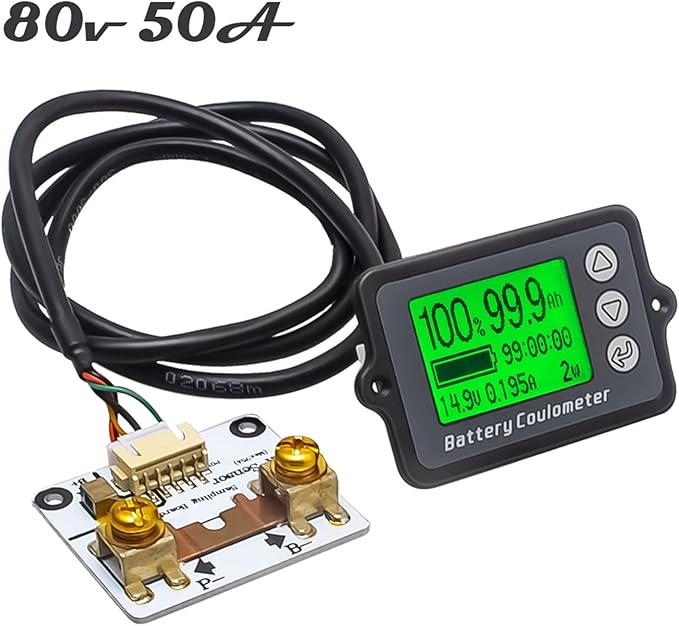
. . . . Since you will be using lifepo4, you will need a coulombmeter, I recommend the tk15 (cost about 50 dollars), its what I use on my 220ah lifepo4. This will ensure you get your battery fully charge everytime. Since this reads the voltage from the battery terminals, you know right away if you have voltage drop problems from the controller to the battery. The reason for a coulombmeter is that lifepo4 voltage is about 13.1 volts from 20 to 90 percent,without counting amps you wouldnt know the actual SOC until its practically empty.
View attachment 31751

I had trouble finding this item because searching for tk15 brought up a lot of different products.
But by using Google image search on your picture of it, I found a version on Amazon at the same price.
Same price you stated.
6177bBPFPYL._AC_SX679_.jpg
 
More changes made to the layout attempting to incorporate suggestions. Also added wire sizes.

As usual any constructive suggestions would be appreciated.
No one seems to have mentioned, most 30 amp charge controllers will handle 400 w of solar panels, but you are operating at near full capacity of the cc. In my research, most people recommend being at least 20% away from maximum on charge controllers.
 
^^Thanks for noticing that, yeah. Two 100 watt panels are fine but doubling that by adding portable panels later on might overwork (and overheat) an MPPT controller rated at 30 amps.

Three options come to mind:

1) Upgrade the 30A controller, now or later

2) use portable panels that have their own onboard controller

3) add another battery or portable battery pack and use a separate controller and solar array for each battery bank (or pack)

Of course there is a 4th option also: Don't add more panels, make do with what you have.
 
What I might do is just get a portable to use with the solar generator and keep that on it's own system. Maybe add one panel to the main setup for a total of 300 watts on that system.
 
since you have an mppt controller its better to connect your panels in series. Mppt requires high voltage panels to extract every amp available. 2x100 watt panels (12 volt panels are actually 21 volt panels) connected in series will equal 42 volts which is perfect for mppt. With the 200 watt panels in good sunlight you should max out at about 10 amps of charge power ( I usually maxed out at 12 amps with a 240 watt panel).
Here is a post that dealt with series versus parallel and it showed an actual improvement in output
https://vanlivingforum.com/threads/is-this-a-proper-amount-of-amps-for-200w-of-panels.41071/

Since you will be using lifepo4, you will need a coulombmeter, I recommend the tk15 (cost about 50 dollars), its what I use on my 220ah lifepo4. This will ensure you get your battery fully charge everytime. Since this reads the voltage from the battery terminals, you know right away if you have voltage drop problems from the controller to the battery. The reason for a coulombmeter is that lifepo4 voltage is about 13.1 volts from 20 to 90 percent,without counting amps you wouldnt know the actual SOC until its practically empty.
View attachment 31751
What is more important than MPPT vs PWM is what the actual charger is designed for.
My own particular MPPT charger has voltage maximum of 25V
maximum total solar power of 660W, which using ohms law,
660 divided by 25= 26.4 amps max at 25 volts.
But it will actually max out at 50 amps, meaning 13.2 volts nominal.
The reason people like to go series with panel for higher volts is cable size.
12V at 50 amps requires a thicker gauge than 24V at 25 amps.
Both of those are the same power in watts.
So if you could pay less for wire, and have a supple thin wire instead of a cable as thick as your thumb, who wouldnt want that?
But as said previous. Series panels suffer from shading issues that parallel panels do not.

TLDR base the decision to go with either series or parallel topology should be based on what the charger specs are, and how long your cable run to the panels will be.
On my van it's 6 feet. So almost no loss, and the cost of the cable was negligible.
 
Top