FALCON
Well-known member
- Joined
- Mar 28, 2015
- Messages
- 500
- Reaction score
- 0
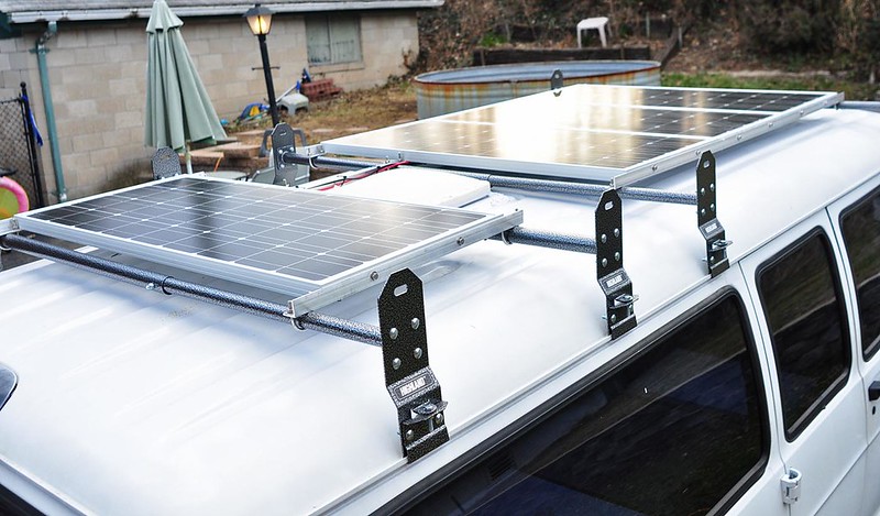
ARRAY INSTALLATION
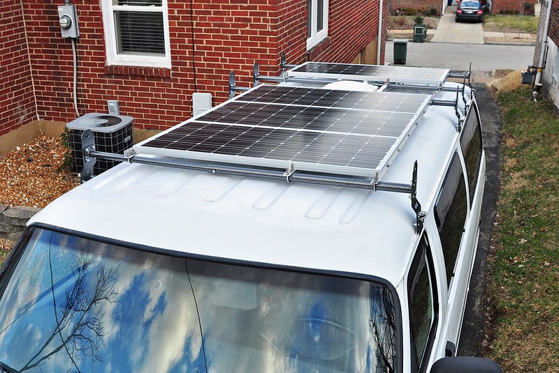
I had been wondering how to get the array up on the van for a while. What I did was par the van at the top of my driveway where there are retaining walls on both sides and along the back. The retaining wall is around 4 feet high so when I stand on it, it gives me good access to the top of the van from all three sides that I needed (drivers side, passenger side, and back).
I asked my girlfriend to help me and we carried the array up from the basement and put it on the van. There is a bar the extends pas the three main panels back to the fourth panel at the rear of the van. I had to bend that in order to get those three panels out while assembled in the frame.
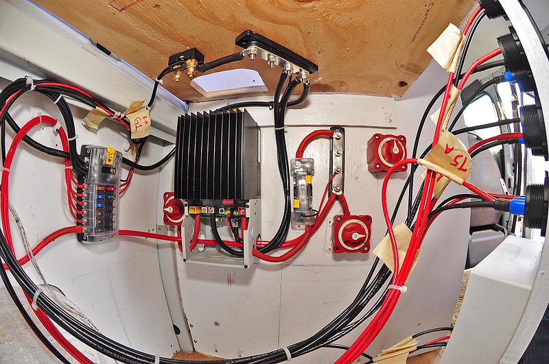
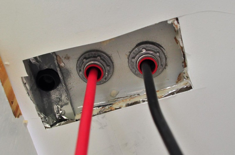
I drilled holes in the roof and put the myers hubs and CGBs in place before this. I messed this up a bit by drilling one hole too close to a roof cross-member. The bottom of the myers hub would not fit. I did have an old plug for my rear differential fill hole and that fits well in the hole. I’m going to use some sealant to seal/hold that in place.
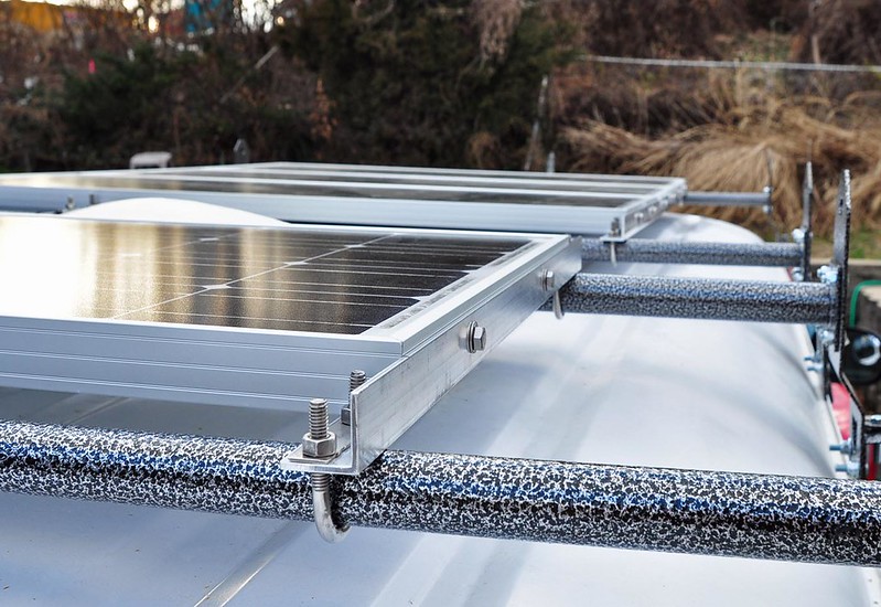
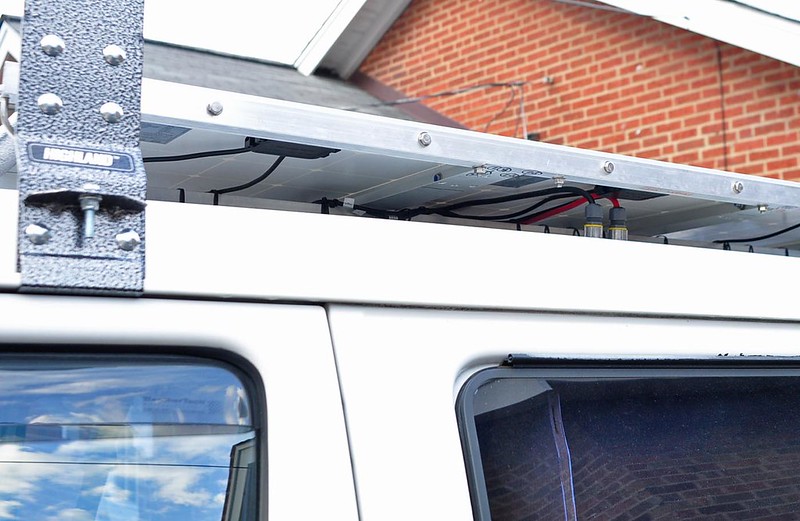
I ran the panel wires along the extra bar that’s under the panels. That seems to work out well.
I definitely liked using the angle aluminum to make the frame. It works really well. If I was doing it again I would use thicker/wider bars. I think mine are 1/8” thick and 1.25” width sides. I would use 1.5” sides because then they would be flush with the top of the panels, and I think a bit thicker stock would work better also.
The three main panels do seem to be held up well enough by the bars. It is aluminum so I suppose there is some slight chance that over time from all the little bumps and such the material will move too much and become more ductile. But I’m not worried about that and I don’t think there would be any immediate failure.
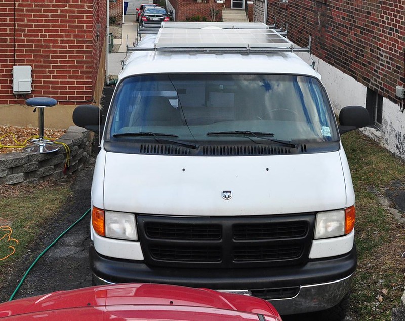
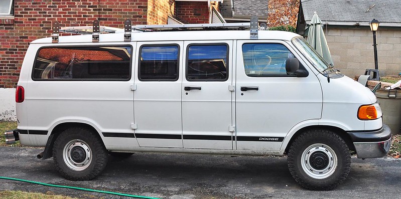
I didn’t do a ton of planning for the roof hole locations. That resulted in the extra hole I had to plug and also in not being able to center the panels width-wise on the van. I think this is a good thing actually because now if I need to go up on the roof, there is room to stand up and walk along the passenger side of the roof.
I put the blue Lock-Tite on the array frame nuts. I may also do the same with the U-Bolt nuts.
I’ve driven a few times now, including on the highway and it seems secure so far. I haven’t heard a single rattle from it or any extra wind noise.

This is inside the van. The black circle on the left is the first hole that was too close to the cross-member.
I had been wondering how to get the array up on the van for a while. What I did was par the van at the top of my driveway where there are retaining walls on both sides and along the back. The retaining wall is around 4 feet high so when I stand on it, it gives me good access to the top of the van from all three sides that I needed (drivers side, passenger side, and back).
I asked my girlfriend to help me and we carried the array up from the basement and put it on the van. There is a bar the extends pas the three main panels back to the fourth panel at the rear of the van. I had to bend that in order to get those three panels out while assembled in the frame.
I drilled holes in the roof and put the myers hubs and CGBs in place before this. I messed this up a bit by drilling one hole too close to a roof cross-member. The bottom of the myers hub would not fit. I did have an old plug for my rear differential fill hole and that fits well in the hole. I’m going to use some sealant to seal/hold that in place.
I ran the panel wires along the extra bar that’s under the panels. That seems to work out well.
I definitely liked using the angle aluminum to make the frame. It works really well. If I was doing it again I would use thicker/wider bars. I think mine are 1/8” thick and 1.25” width sides. I would use 1.5” sides because then they would be flush with the top of the panels, and I think a bit thicker stock would work better also.
The three main panels do seem to be held up well enough by the bars. It is aluminum so I suppose there is some slight chance that over time from all the little bumps and such the material will move too much and become more ductile. But I’m not worried about that and I don’t think there would be any immediate failure.
I didn’t do a ton of planning for the roof hole locations. That resulted in the extra hole I had to plug and also in not being able to center the panels width-wise on the van. I think this is a good thing actually because now if I need to go up on the roof, there is room to stand up and walk along the passenger side of the roof.
I put the blue Lock-Tite on the array frame nuts. I may also do the same with the U-Bolt nuts.
I’ve driven a few times now, including on the highway and it seems secure so far. I haven’t heard a single rattle from it or any extra wind noise.
This is inside the van. The black circle on the left is the first hole that was too close to the cross-member.