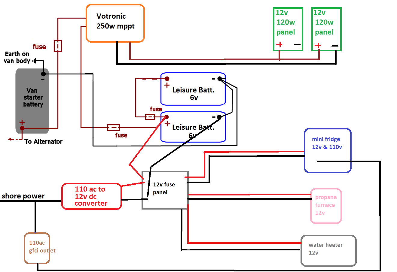
CamperVan wiring schematic. plz peer review!

Van Living Forum

Help Support Van Living Forum:

This site may earn a commission from merchant affiliate links, including eBay, Amazon, and others.

JoRow

Active member
Joined
Jun 26, 2016
Messages
39
Reaction score
0
Can you guys look at this rough draft of how I'm planning on wiring up my campervan? I'm a total noob when it comes to this. I'm pretty sure that I'll need to add diodes all over the place and I'm still figuring out my components so I left the fuse sizes blank. Any and all input is appreciated!

3yLku2T.png
 
JoRow said:
Can you guys look at this rough draft of how I'm planning on wiring up my campervan? I'm a total noob when it comes to this. I'm pretty sure that I'll need to add diodes all over the place and I'm still figuring out my components so I left the fuse sizes blank. Any and all input is appreciated!

3yLku2T.png

I think your house batteries are wired wrong .
Also,,  I don't think you need any wiring going to the starting battery unless you plan to use a battery isolator/solenoid
 
Mobilesport said:
I think your house batteries are wired wrong .
Also,,  I don't think you need any wiring going to the starting battery unless you plan to use a battery isolator/solenoid


If I pop an isolator/solenoid in there Can I use the alternator to charge the leisure batteries? That's what I'm going for


Sent from my iPhone using Tapatalk
 
JoRow said:
If I pop an isolator/solenoid in there Can I use the alternator to charge the leisure batteries? That's what I'm going for


Sent from my iPhone using Tapatalk

It can do part of the job , I have mine hooked up so the alternator chargesthe house batteries but I charge them alot using a battery charger so I don't have to work my alternator so much
 
Mobilesport said:
It can do part of the job , I have mine hooked up so the alternator chargesthe house batteries but I charge them alot using a battery charger so I don't have to work my alternator so much

The battery isolator comes with instructions on how to wire it up
 
JoRow said:
If I pop an isolator/solenoid in there Can I use the alternator to charge the leisure batteries? That's what I'm going for


Sent from my iPhone using Tapatalk

It's very practical to do so and not at all expensive. The isolator/solenoid that is - the wiring can be quite expensive depending on how long a run you have to do to get from the engine compartment/starting battery/isolator to the house batteries.

How valuable it will be will depend on how much driving you're doing.

It will also prevent you from running down the starting battery when you're using power from the house battery system.

There is a whole section here on wiring for electrical. It's really good reading and will explain a whole lot of stuff!
 
To follow up with what Mobilsport pointed out, your house batteries should be wired in series to give you 12 VDC, not in parallel which only gives you 6 VDC. Positive to negative, like batteries in a flashlight.
 
Almost There said:
It's very practical to do so and not at all expensive. The isolator/solenoid that is - the wiring can be quite expensive depending on how long a run you have to do to get from the engine compartment/starting battery/isolator to the house batteries.

How valuable it will be will depend on how much driving you're doing.

It will also prevent you from running down the starting battery when you're using power from the house battery system.

There is a whole section here on wiring for electrical. It's really good reading and will explain a whole lot of stuff!


I'm basically just trying to restore an old system that was already in place and add solar panels. It actually had wires running from the engine compartment to the back already. Does this look like an isolator here? A very very old isolator? HahaImage1467659808.816879.jpg


Sent from my iPhone using Tapatalk
 

Attachments

  • Image1467659808.816879.jpg
    Image1467659808.816879.jpg
    301.5 KB
One of the problems with diode based battery isolators is the significant voltage drop between the input (coming directly from the alternator) and the outputs (going to the various battery banks).

There is a technology solution to this problem. Jamestown Distributors, the boat people, sell a battery isolator using a field effect transistor which results in no voltage drop between the input and outputs. The isolator looks at each battery bank for low voltage and charges each one automatically as needed. It is more convenient than a manual solenoid, but costs more. I've used one in my Peterbilt Motorhome for the past six years and have been very pleased with the way it works.

Just my opinion . . .
 
There should be a fuse on the leisure battery output going to the DC panel. If the cable between the battery and power distribution panel were to chafe and short out, you would have one heck of an arc welder. Anything flammable in the area like carpet, would surely catch fire.

I don't know if you understood about the batteries being wired wrong. If those leisure batteries were both 12 Volt, then the way you have it would be correct.
That solenoid in your picture looks like it might allow charging of house batteries from the alternator. Without knowing where those wires go, it is impossible to say for sure. Also if you use a heavier gauge wire for this interconnect, you can use a larger inverter and run your vehicle when you want to use something heavy like a microwave. Make sure that the vehicle battery also has a fuse in the line going to solenoid. If any wire anywhere shorts out, you want a fuse to blow. Wire sizes are important, What were you going to use where and with what size fuses, Also include what size inverter you planned on.

There should also be a selector switch that disconnects the shore power outlet when the inverter is active. Also it would protect the inverter when plugged into shore power. This could be as simple as having a plug on the line going to the outlets and a receptacle at the inverter. When you want inverter, plug it in there, when you are on shore power unplug it from the inverter and plug it into your extension cord.
 
JoRow said:
I'm basically just trying to restore an old system that was already in place and add solar panels. It actually had wires running from the engine compartment to the back already. Does this look like an isolator here? A very very old isolator? Haha


Sent from my iPhone using Tapatalk

Uhhh, yep that's what that is...a very, very old 4 wire solenoid switch.

Have someone stand outside the vehicle near that switch and listen when you start the engine. It should make a clicking sound. If it does, it's actually still working. If not and since it looks like something the cat dragged in a couple of decades ago, replace it with another 4 wire solenoid. IIWM, I'd trace the wiring and if there's any doubt about the wiring, replace it while you're at it.
 
Thank you all so much. I'm learning a lot here. I'm going to try and process all of this and edit my schematic tonight. I'll also start filling fuse sizes, more specific components and length of runs.


Sent from my iPhone using Tapatalk
 
one other point your solar charge controller will have a + and a - output. run the hot to one battery and the ground to the other battery. do the same for your battery outputs run the hot from one battery and the ground from the other. this helps keep the batteries in balance. that is a dual battery solenoid. a new one will look the same only new. like Speed Highway said there are other options but I would stay away from the diode based ones. highdesertranger
 
That type of solenoid can come in two different versions. Momentary duty and continuous duty. The momentary duty has a stronger coil to close the contacts for heavy current use like a starter motor. It will use more power and may even get hot if powered up all the time. The continuous duty relay has a smaller coil, uses less power, stays cool, but can not carry heavy loads. What I used, (and seems to work well), is http://www.ebay.com/itm/401111987343?_trksid=p2057872.m2749.l2649&ssPageName=STRK:MEBIDX:IT
 
Selecting the components you want to use is the easy part. Its connecting them all together that's hard. Each component can have different connection types and sizes that need to be researched. There could be a mix of both 5/16" and 3/8" studs that need to be thought out.

The documents that came with ALL your components should have examples on how to connect them. I would recommend pulling them together for a very high level block diagram, then fine tune it from there. A virtual build on paper will result in a component list that brings it all together.  

Regarding isolators and solenoids to charge your house batteries, battery banks of different chemistries require different charging rates. Its wise not to mix them unless the correct charging profile is used.
 

Latest posts

Top