FALCON
Well-known member
- Joined
- Mar 28, 2015
- Messages
- 500
- Reaction score
- 0
I’m doing electrical system design and want to run my wire sizes by you guys.
SYSTEM INFO
Solar Panels: 4 x 100w Renogy.
- Rated voltage: 18.9v
- Rated current: 5.3 amps
- Current at NOCT: 5.9amps
Charge Controller: Morningstar Tristar MPPT 30amp
(max cable size AWG2)
Inveter: Samlux 600w pure sine.
Battery or Batteries: 200 amp-hours total at 12v. Likely AGM
WIRE SIZE DESIGN
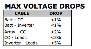
Here are the system design voltage drops I used:

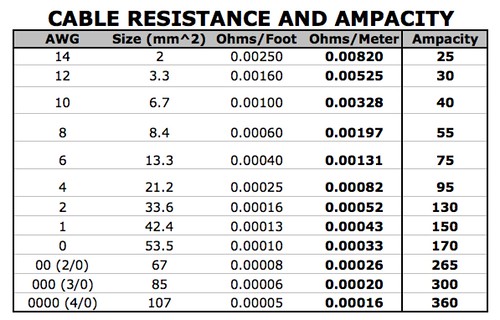
Wire info:

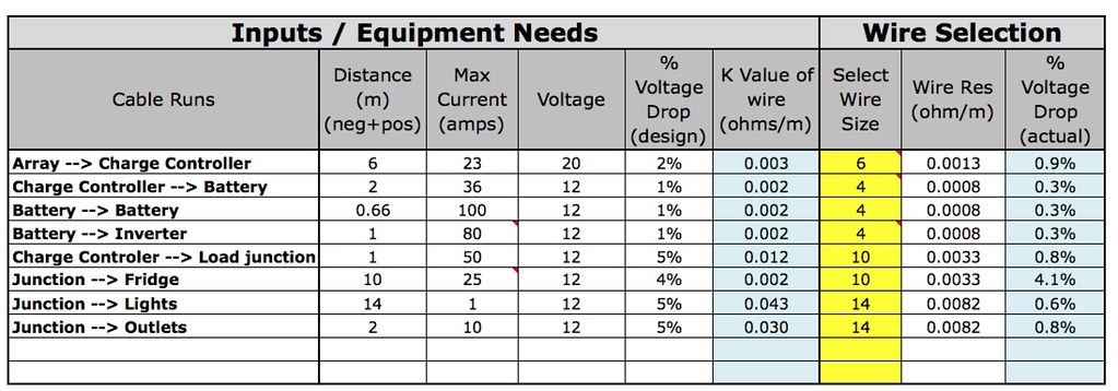
And my design calculations: (Access to this spreadsheet came along with the book “Stand-Alone Solar Electric Systems” by Mark Hankins. It was a very helpful book for a beginner like me.)

The “K value of wire” cell is calculated based on the inputs that are to the left of it. Then in the “Select wire size” column, I’m choosing a wire size that has less resistance, and then the last column is a voltage drop calculation for the wire size I’ve selected.
First - overall - if it looks like I’ve done something wrong wish my wire size selection, please let me know.
There are some things that I’m not so sure about:
In case anyone is wondering, here is the formula for voltage drop:
Resistance = (%Voltage drop) * (Voltage) / [ (length) * (current) ]
Voltage drop % = (Length) * (Current) * (Resistance/m) / (Voltage)
* Length = cable run, the length of positive and negative cables added together, in meters
* “Resistance/m” is Ohms per meter
SYSTEM INFO
Solar Panels: 4 x 100w Renogy.
- Rated voltage: 18.9v
- Rated current: 5.3 amps
- Current at NOCT: 5.9amps
Charge Controller: Morningstar Tristar MPPT 30amp
(max cable size AWG2)
Inveter: Samlux 600w pure sine.
Battery or Batteries: 200 amp-hours total at 12v. Likely AGM
WIRE SIZE DESIGN
Here are the system design voltage drops I used:

Wire info:

And my design calculations: (Access to this spreadsheet came along with the book “Stand-Alone Solar Electric Systems” by Mark Hankins. It was a very helpful book for a beginner like me.)

The “K value of wire” cell is calculated based on the inputs that are to the left of it. Then in the “Select wire size” column, I’m choosing a wire size that has less resistance, and then the last column is a voltage drop calculation for the wire size I’ve selected.
First - overall - if it looks like I’ve done something wrong wish my wire size selection, please let me know.
There are some things that I’m not so sure about:
- How many amps to use for the voltage drop calculation for the battery to battery cables (if using multiple batteries).
- Some people use or recommend using HUGE cables to/from the batteries (like AWG 00 (2/0). Am I missing something here?
- For the wires going to the generic DC load outlets, I wasn’t sure how many max amps to use, so I just put 10. (??). I may just use AWG10 wire since I may use that for another run.
In case anyone is wondering, here is the formula for voltage drop:
Resistance = (%Voltage drop) * (Voltage) / [ (length) * (current) ]
Voltage drop % = (Length) * (Current) * (Resistance/m) / (Voltage)
* Length = cable run, the length of positive and negative cables added together, in meters
* “Resistance/m” is Ohms per meter


