Pics of your continuous duty solenoid. Please!

Van Living Forum

Help Support Van Living Forum:

This site may earn a commission from merchant affiliate links, including eBay, Amazon, and others.

TooManyDogs

Well-known member
Joined
Nov 7, 2015
Messages
164
Reaction score
0
Hi everybody!

I'm in the process of installing my CD Solenoid but am having a hard time finding a place under the hood to mount it. Can you post a pic or description of how yours is setup? Did you have to move or take anything apart to squeeze one in? I'm almost to the point of zip-tieing it to...something. Maybe to holes drilled out in the metal somewhere. Help!
 
Zip tying it isnt going to work, it needs to be well grounded to work properly.

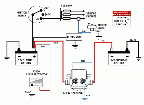
Typical wiring diagram
projecta.gif
 
I have all the parts and it will be wired in and grounded correctly. What I mean is that I can't find a convenient physical location to mount it.
 
To get the solenoid and the fuse block in place, John had to take out the battery to give him enough room to work.

Both are mounted on the inner panel of the side wall right beside the battery.

He carefully positioned the fuse block holder so that it can be accessed without removing the battery but it's tight!

I don't have pictures of it but if you really need them I can take a couple tomorrow...losing light here fast! Best I can do for pics is another beautiful AZ sunset.... :D
 
If it's not too much trouble, I would really appreciate it, Beth! Did John have to drill into anything to mount them? I took my battery out and I'm not sure there's room to squeeze the CD Solenoid between it and the sidewall. I wish the solenoid wasn't so fat!
 
Well, it was a relacement solenoid so John didnt have to drill the holes but the first one that was installed had to have screw holes drilled yes.

Sorry for tyos, I seem to have lost a coule of keys on the keyboard for the time being...haha, I cant show you which ones they are because they dont work.... :rolleyes: , Okay the letter beside o and the aostrohe below it...oh this sucks!!.... :D :D
 
here is what mine looked like when i got it but it is a 1977 so no gadgets and plenty of space so i dont think it will apply
002_1.jpg
 
poncho62 said:
Zip tying it isnt going to work, it needs to be well grounded to work properly.

Typical wiring diagram
projecta.gif

The surge protector small red wire and the larger red wire that supplys current to the solenoid both should have correctly sized fuses or circuit breakers within 7" of the positive terminal of the starting battery.  On the red wire that takes current from the solenoid there should also be a fuse or circuit breaker within 7" of the positive terminal on the aux battery.

I would also run a fat ground wire from the starting battery to the aux battery.  I'm just not comfortable with relying on chassis grounds with something as important as making sure that the aux battery gets as much voltage as possible by eliminating as many potential points of voltage drop.
 
Most hand held cordless drill/drivers will fit in a battery space.  

I make sure every solenoid is protected with a quality fuse.  Look to durability over style in the fuse holders.  The expensive fancy units have more parts to melt or break. 

Here is my unit.  I chose to have it separate in an electrical box.  Also, inside the van where I can access everything.
 

Attachments

  • Solinoid.jpg
    Solinoid.jpg
    90.6 KB · Views: 16
There is no rule that the solenoid has to go in the engine compartment. Nor is there any rul that says power for th esolenoiid needs to come from Engine battery.

When You take power from the Engine battery, to fuse, to solenoid to fuse to house battery, It is a longer circuit than

Alternator to solenoid to Fuse to House battery..

This will shorten the house battery charging circuit
This will require one less fuse as the OEM charging circuit si already fused and will not be carrying any additional current, and does not need to be upgraded

ZGoing from Alternator to Solenoid to House battery is a shorter circuit The Vehicles voltage regulator will see that it requires more field current to get system voltage higher, andhopefully allows 14+ voltage to happen for longer, recharging house battery faster.

Bypassing the OEM charging circuit(Alternator to OEM FUSE to engine battery) will boost charging performance, as this cable is too small when depleted batteries are tacked onto the engine battery.

Just stack another ring terminal on the Alternator (+) output, and mount the solenoid under the body inline between alternator and house batteries( if in the back of Van/Vehicle in the Shortest circuit possible. You can run a ground cable from house battery to Alternator mounting bolt at the same time, and then not have to worry about the problematic frame grounds, And charging amps will likely also be higher too.

Eliminate the middle man, and one fuse. Take power from Alternator (+) stud for solenoid instead of engine battery. It simply works bettery for your battery, and will save money on Copper, and one fuse and fuse holder.

Taking power from the Engine battery requires the original OEM charging circuit carry more amps for longer than it was intended to do so when House batteries are tacked onto the end. Skip the engine battery, Take power from alternator (+) output stud, get more amps, spend less money easier and shorter cabling and one less fuse. Win Win win and Win, for the win.
 
Agreed on my 2007 Ford E-150 I connected to the output of the alternator(was a pita and had to mod the insulator for larger ring terminal) then came out to the solenoid on the fire wall and back to the house battery. Since the house battery has a disaster breaker on it that protects that line as well.
 
Not meaning to hijack the thread, but I do have some confusion...

Some installs reference a "continuous duty solenoid" and a "battery isolator"

Are the same thing? Do they do the same functions?
If not how do they differ?

I realize I'm just getting started, but... PLEASE help and hopefully clear up some confusion?
 
galladanb said:
Not meaning to hijack the thread, but I do have some confusion...

Some installs reference a "continuous duty solenoid" and a "battery isolator"

Are the same thing? Do they do the same functions?
If not how do they differ?

I realize I'm just getting started, but... PLEASE help and hopefully clear up some confusion?

A solenoid is just a heavy duty electrical relay, using a small current to fire and electromagnet to hold two larger contacts together, in this case, the two fat battery cables putting engine and house battery in parallel when the engine is running

A solenoid can be termed a battery isolator, if wired as one, but in general isolators refer to a Diode based units which have a Diode in them only allowing electric flow from alternator to house battery.  These unfortunately drop the voltage and slow the recharging almost ensuring bad battery performance. Diode based isolators have large finned heatsinks to turn that wasted voltage into heat.  

There are a thousand products along these lines. The Simple CD solenoid  cheapest.  Some solenoids are 'smart' and are actuated by charging voltages instead of a dedicated circuit which becomes live with engine running.
 
Top