Am I getting this right?

Van Living Forum

Help Support Van Living Forum:

This site may earn a commission from merchant affiliate links, including eBay, Amazon, and others.

Toes

Active member
Joined
Nov 23, 2013
Messages
30
Reaction score
0
Hey everyone,

First just wanted to say thanks to everyone for the help so far. I'm learning SO MUCH for this forum!

I want to make sure I have a solid understanding about electrical stuff before I start purchasing items and delving deeper.
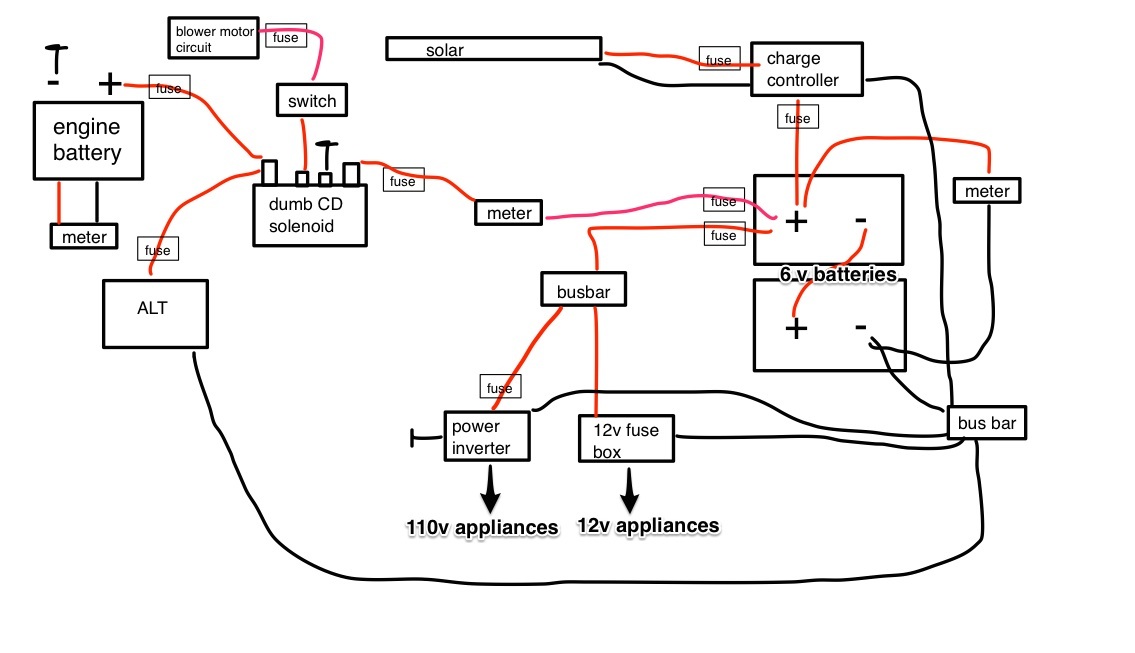
I'm a very visual person so I've drawn out to the best of my understanding what I need for my system.

So my my questions to you is....
Am I understanding this right?
Is there anything I'm missing?

BpjmkGr.jpg
 
You need to run a ground wire from your house battery to the chassis. Otherwise, no current will flow from your alternator into the house batteries because there will be no return path back to the alternator.

Likewise, the solar panel will have plus and minus wires running to the controller, and the controller will have both plus and minus wires going to the battery.

The inverter will have THREE heavy wires - plus and minus to the house batteries and a separate ground wire to the chassis.

Most importantly of all, you are not showing any circuit breakers or fuses.

The plus wires going into and out of the solar controller need fuses or breakers.

The plus wire going to the inverter needs a heavy, fast-acting fuse.

The wire from the alternator to the house batteries needs fuses on BOTH ends.

Regards
John
 
Looks about right but I see that you have 2 six volt batteries. Thats good but you do need to fully understand what is required here. I dont know how much you have learned so far so I'm not preaching on you. Often times its taken for granted on the charging end of things. You will need the ability to hammer the batteries back up to 1.275 SPECFIC GRAVITY. I'm not yelling at you, I'm giving you an important tip. You must understand specific gravity of the battery if you want good battery performance and long life. For example you could drive for an hour or 2 and charge your battery. If you checked the voltage right away it might be 13 plus volts. As it sits for awhile or you start to apply a load it will come down to about 12.6 and thats the fully charged voltage. The problem is that the specific gravity of the battery may not be all the way up and the battery will soon be dead. When I say dead I mean 12 volts.
If you were to continue to do this to the battery cycle after cycle it would sulfate the plates. The battery needs to reach a point of gassing so that the electrolyte solution mixes and prevents stratification. I have 12 volt batteries that are charged to 15 volts. They are 7 years old and still pump out lots of power.
Read up on
stratification
sulfation
bulk charge
absorption charge
float charge
equalize charge
checking specific gravity. This is important.
Read and understand why you dont want to continually discharge below 12 volts or so.
proper protective wear while working with batteries GOGGLES. YES I yelled that part. :) You will be working with sulfuric ACID
Batteries procuce HYDROGEN GAS when charging and discharging. Any spark or igntion source near the top can blow the top of the battery out like a bomb going off. I have seen it several times and its ugly. They are not toys. Again, not preaching, just dont want a blind mini van driver on the road with me.


http://www.marxrv.com/12volt/12volt.htm
 
Why is it good to have 2 six volt batteries instead of 1 twelve volt battery?
 
6v golf cart batteries are true deep cycle batteries, originally designed that way. They have been around a long time, they are bought by the pallett load by gold courses, they are likely the best bang for the buck lead acid deep cycle battery available.

12v batteries are kind of a compromise, trying to stuff deep cycle construction into a 12v standard size Starting battery Jar/case.

The true 12v deep cycle batteries are pricier, harder to find, and despite saying "deep cycle" and RV on them many 12v batteries marketed as deep cycle batteries, they are just dual purpose or marine batteries, which are closer to starting batteries than a deep cycle battery. A true deep cycle 12v battery will be about 15 to 25% heavier and and 30% more expensive than a Marine battery. If in doubt, bring your bathroom scale.

Also the larger 12v true deep cycle batteries Group size 27,29,31, seem to require more voltage and more time to return the Specific gravity back to the maximum. Voltage up and beyond most chargers abilities.

The GC batteries are less petulant, require less baby sitting, and are pretty tolerant of the battery abuser.

Most fuse boxes are (+) only. Some might allow you to attach grounds but they are not fused. The ground section It is more like a Buss bar.

Grounding the house batteries to the chassis is imperative. One can also ground them directly to the alternator (-), which is better in the long run, as chassis grounds are very problem prone if meticulous care is not taken in cleaning the mating surfaces, and then sealing them from oxygen.
 
PastTense said:
Why is it good to have 2 six volt batteries instead of 1 twelve volt battery?
6 Volt 'golf cart' batteries are easy to find deep cycle batteries. 12 volt deep cycle batteries are harder to find, usually more expensive than two 6 volt, and approximately twice the weight. It is easier to handle two 60 lb. batteries than one 120 lb. battery. -- Spiff

Drat you, SternWake, you beat me while I was verifying the weight of the batteries!
 
Optimistic Paranoid said:
Most importantly of all, you are not showing any circuit breakers or fuses.
The plus wires going into and out of the solar controller need fuses or breakers.
The plus wire going to the inverter needs a heavy, fast-acting fuse.
The wire from the alternator to the house batteries needs fuses on BOTH ends.

Thanks for the info, John, I will revise the schematic. Can you tell me where exactly fuses and circuit breakers should be placed in the system?

DirtCheap - thanks for all the info! I appreciate you sharing specific terms as I often don't even know what specific words I should be searching on google.
 
I would get rid of the voltmeter across the house bank.
Is the solenoid connected to the ignition so it connects when running and disconnects when engine is off?
You could run the house battery positive to a buss bar with a heavy fuse and then the loads taken from the buss bar with smaller fuses. Some use the heavy fuse on the negative at the house battery before the chassis ground.
There is a lot of good information on the cruising boat people sites. Here is one; http://c34.org/bbs/index.php?PHPSESSID=716980e0588a6c59a6f8564a756da597&/topic,5977.0.html
 
At the same time you should not be afraid of using a 12 volt deep/marine. They are a good cheap option. As I said, I have some that are 7 years old. The big difference is how they are charged and discharged. You also dont want too many amps of capacity if you are charging with solar as the panel area of your roof wont give you the capacity to properly charge. Again search sterns stuff as he has covered that. It seems good to have lots of batteries but on the other end they have to be recharged and it takes far longer OR it takes mega input. Solar or rv converters are not going to hammer your batteries full in a short time. It takes an industrial type battery charger. You cant hammer a battery full and raise the sg with a 10 pound battery charger, it takes a 35 pound battery charger.
So.....too much battery can hurt you, as you wont have the capacity to properly return it to 1.275. You need a battery charger that will approach 15 volts.
As others have said knowing what your needs are is an important part but going back to your original post it seems that you wanted the most basic of stuff right now because of your situation. Its really important if you are putting out big money for the systems, you dont want to buy components multiple times as you experiment. On the other hand if you are going very small and just trying to sort of survive right now you can wing it to some extent. Let me imagine being in a van or rv and trying to keep it as simple as possible.....I would buy a deep/marine 12 volt, some sort of digital meter (fixed or portable), a fused lighter socket, say 2 led bulbs, small 12 volt fan, A fused switched lead to the alternator and about a ten amp cheap portable battery charger. The vehicle would give me a lot of my power but at some interval I would need to plug in to top off the battery (Some means of parking where you could plug in or take the battery into work etc.). The better and more involved option is GOOD solar products.

In a piece meal approach I haven't invested much as my knowledge and system grows. When you get to the solar, I would be careful to get the right stuff. Its not like saying I dont want this $6.00 switch for my alt circuit, its like I spent $100 for this controller and now I want the right one for $200. I have inverters laying around because of this.
I originally bought this gadget called a fuse buddy to help find system drains on electric vehicles and equipment. It can plug into a fuse holder or I have used it between the ground cable and the frame to watch the system load as different things are turned on.
http://www.sears.com/electronic-spe...36-2&sid=IDx20070921x00003d&redirectType=SRDT

I'm almost done and I will shut up :).
I noticed someone else saying that you can just use your alternator and get to 85 % or so on your battery and when its junk just buy another one. This is probably true although I'm not sure of the time frame that it would last it may be something you could live with. What someone like stern is saying and I'm building right now is a system that works day after day and never makes you compromise. I'm in an rv and not a van but I want to walk in and turn on anything I want. I want lights, tv, playstation, water pump, showers, cold refrigerator and the energy beast of them all, an RV FURNACE, AND I dont want to plug in. It can work, it just takes $5,000. Its the same in a van, just a different scale.
 
Zil said:
I would get rid of the voltmeter across the house bank.
Is the solenoid connected to the ignition so it connects when running and disconnects when engine is off?
You could run the house battery positive to a buss bar with a heavy fuse and then the loads taken from the buss bar with smaller fuses. Some use the heavy fuse on the negative at the house battery before the chassis ground.

Zil, I'd like to connect the starter battery to the solenoid and wire in a manual switch, that way I can have control over when the solenoid is sending juice to the house batteries. This will allow me shut off the solenoid so it's not using any power when the switch is off.
At least I thin that's how it should be working... :)
Also, what's a buss bar? Google isn't being much help with this one...
And thanks for the link!

DirtCheap, Yes I was thinking at first that I'd like to go the cheapest route, but as I read and research, I'm thinking that I'd like to get the best that I can up front so I'm not having to spend more money down the road. I probably will also hold off on getting solar right away, but I'd like to have other components in place so when i upgrade to solar, I won't have to change anything out to accommodate a solar setup.
Also, I don't think this is going to be a temporary thing. Eventually I'd like to upgrade to a bigger van (so I would like to keep my first system as modular as possible), but once I move out of my apartment, I don't see myself going back any time soon.
 
A Buss bar or a Buss stud is a common distribution point. So instead of wiring 12 individual circuits to the battery (-), one can run one fatter wire to the battery (-) from the Buss bar/Stud and all the thinner wires to the buss.

http://www.amazon.com/BB-4S-150A-DS...UTF8&qid=1403545222&sr=8-7&keywords=buss+stud


Full manual control of a dumb solenoid is easy. Just use a lighted toggle switch. One can also take the 12v(+) from the blower motor circuit and run it through the lighted toggle switch. This way, with the engine off, key out of the ignition the solenoid will be disconnected no matter the position the switch is left in.

This solenoid activation circuit needs to be fused too. Deciding where to pull the 12v for the activation circuit is what trips most people up. Full manual control is easy as one can just take 12v(+) from either battery(+), but pulling from the blower motor circuit requires a bit more. If the Vehicle uses ATC/ATO blade style fuses, then this product makes things easy:

http://www.amazon.com/Littelfuse-FH...1403545563&sr=8-1&keywords=ATC+ATO+add+a+fuse

Just plug it into the blower motor circuit and use the extra feed to run to the lighted toggle switch.

I have glass barrel type fuses from Dodge, and will admit to an improper crushing of stranded wire into the fuse holder itself, but for my aftermarket tachometer. I don't employ solenoids for battery isolation in my Van


If one does not want to crush stranded wire under a glass fuse, and does not have the ATC fuse holders from the factory, and does not have the skills to tap the blower motor circuit wire properly, then the following product can be used.

Let me state I think this is a bad idea. I bring it up only to help the gears click into place about what is needed to tap into an existing circuit.
http://www.amazon.com/Install-Bay-3...=UTF8&qid=1403546015&sr=8-1&keywords=wire+tap

When snapped over a wire, this device pierces the insulation and touches the wire stranding. It can also break some stranding and cause a point of resistance. The former owner of my Van used these to wire in a trailer harness and every tap severed half the wire strands, and caused serious brake light and signal light issues until I removed the sections of wires he used the products on.

The Blower motor circuit is usually fused at 20 or 25 amps and uses 10 or 12 awg wire, making the above product an extremely bad idea for tapping into the circuit.

Here is an example of my tapping into a wire( 2 wires actually), without having to cut the original wiring.

Carefully strip the insulation for about 3/4 of an inch in the middle of the wire. Make sure not to sever any stranding. Using an Awl or similar tool, open up a hole in the center of the stranded wire. Poke the New wire for the additional circuit through this hole, and wrap it around the other wire.

007copy2_zpsdd53475e.jpg


I soldered mine after the fact, and then used several layers of liquid electrical tape. One can forgo the soldering since the space to do so will be tight, and use electrical tape( quality) and use some small Zip ties to hold the new wire to the old to keep the stress off the area which was tapped.

One should do this with a fuse with pigtails. One of the Pigtails piercing the wire.

http://www.amazon.com/In-line-ACT-W...id=1403546899&sr=1-2&keywords=atc+fuse+holder


Here are some pics showing how I tapped my OEM alternator(+) wire to feed my nearby headlamp relays.
Stock6awgalternatorbatteryfeed_zpsf02f0d0d.jpg


alternatoroutputspiral_zps9cdc23ab.jpg


tappedalternatorfeed_zps475964d1.jpg


relayalternatorfeedsoldered_zps2b915eed.jpg


Hope this addresses the questions you asked in the PM
 
Unless you're pretty sure you know what you are doing, starting out with a cheap system is not a bad idea. Odds are good that even cheap solar panels will last for decades. Cheap controllers should last a few years and then they are only $30 to replace. Walmart marine batteries have a great warranty and you can probably fully replace them. But a cheap PWM controller will throw away 30-40% of your power.

Once you've got a pretty good handle on it you can start upgrading the parts with better components and growing the system as well.
Bob
 
Toes said:
Thanks for the info, John, I will revise the schematic. Can you tell me where exactly fuses and circuit breakers should be placed in the system?

The rule of thumb is as close to the power source as possible, and certainly before the wire goes through a firewall.

I believe on boats, the legal requirement is that the
main power fuses need to be within 18 inches of the battery.

Now, understand, that doesn't mean that the fuse block has to be within 18 inches of the battery. They are saying that the heavy power wire that carries current from the battery TO the fuse block has to be fused within 18 inches of the battery. The fuse block can be anywhere.

Here's a quick and dirty list of wire sizes and the MAXIMUM size fuse or circuit breaker you can safely use on that wire.

16 AWG - 10 amps
14 AWG - 15 amps
12 AWG - 20 amps
10 AWG - 30 amps
8 AWG - 50 amps
6 AWG - 80 amps
4 AWG - 125 amps
2 AWG - 200 amps
1 AWG - 250 amps
0 AWG - 325 amps
00 AWG - 400 amps

Do NOT, under any circumstances, ever use a bigger fuse than is listed. The wire will start a fire before a heavier fuse ever blows.

The literature for your inverter will probably tell you what size fuse to put on the positive feed. It will also probably suggest what size wire to use. By all means, go for a bigger wire than they suggest if you want, but stick with the fuse size they recommend, even if the wire could handle bigger.

And remember always the first rule of electrical design - An unfused circuit is a fire waiting to happen.

Regards
John


BTW, take a look at the website of

A M Solar

Lots of good info there.

Check out this diagram from that site:

http://www.amsolar.com/shop/images/8-srs_60mppt2.v1.14.pdf

Regards
John
 
Thanks so much for the info, everyone!
I think I'm starting to get a better handle on all this. It's crazy how you don't have to think about or know any of this stuff when you just walk into a room and flip a switch.
Gives me a lot more respect for my current level of consumption.

I should also clarify that I probably won't be incorporating this system all at once. For instance I'll probably add the solar later. But this is more or less the basics of my ideal setup, so I want to make sure I understand where I'm going so I can make better decisions when starting out.

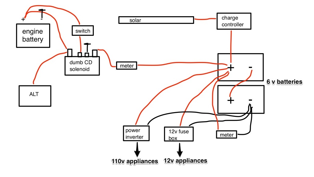
Here's my revised setup.
E2WFpW6.jpg


– Toes
 
If you get a negative bussbar, then there is no need to have a Fuseblock with an incorporated (-) buss bar, and no need to run any(-) to the fuse block.

All 12v appliances will have one wire(+) going to fuse block and the (-) going to the (-)buss bar.

The Voltmeters will have 3 wires, (+), (-) and (voltage sense(+)), The (+) should have a fuse on it too, and perhaps a toggle switch. They can be very bright, and will consume some amount of battery power too.

Do note voltmeters are not like a fuel gauge, unless the battery has not seen charging or discharging for many many hours. Still a useful tool, but if the battery is under a 10 amp load and reads 12.0 volts, well when all the loads are removed, that voltage might rebound to 12.5v.

12.0 v is less than 50% on most voltage state of charge sharts and 12.5 is generally 80 to 90% charged, so one must take voltage readings with a grain of salt. With experience over many discharge cycles you can guess fairly accurately as to state of charge, but a first glance means,......not too much, and this throws off a majority of newbies to battery living, especially when they shut off the engine and see 13+ volts, because of lingering surface charge.
 
Ideally, the inverter should be as physically close to the batteries as possible, without actually being in the same compartment. The batteries give off fumes that are corrosive and will - eventually - destroy electronics. The batteries also give off hydrogen, and inverters are usually not ignition safe.

You want the shortest possible dc connection. The ac wires can be any length you need.

Finally, some people like to incorporate a master off-on switch in their dc system. Not absolutely necessary, but a nice touch.

Regards
John
 
Good question... how do I find this info?

SternWake said:
The Voltmeters will have 3 wires, (+), (-) and (voltage sense(+)), The (+) should have a fuse on it too, and perhaps a toggle switch. They can be very bright, and will consume some amount of battery power too.

Stern, is there such a things as a voltmeter that doesn't use any power but only measures the power passing through it?
 
Top