About to install my Solar system... I have a few questions.

Van Living Forum

Help Support Van Living Forum:

This site may earn a commission from merchant affiliate links, including eBay, Amazon, and others.

One Awesome Inch

Well-known member
Joined
Nov 14, 2013
Messages
1,170
Reaction score
0
I finally have all the components to install my solar system.

Renogy 100w flexible panel
Charge controller
Blue Seas 6 circuit fuse box

I still need to buy the wire. If I use 10 gage rather than 12 gage from the battery to the charge controller will that increase the power I get from the solar panel? I think I read that somewhere but can't quite remember.

What gage wire do I use from the solar panel to the charge controller... 16g?

Since I am using a dual marine/rv battery that is in the engine compartment (acts as both starting battery & house battery), I will need to drill a hole through the firewall of the van so I can run the appropriate cable through it. Any suggestions as to where to put that hole? I really dont want to wreck anything.

Much appreciate any assistance you can give. :)
 
It won't increase the power, it merely won't decrease it as much over the same distance as a thinner wire would.
 
Plus you can handle more amperage with a thicker wire if you ever add panels
 
Here's a link to a Voltage drop calculator.  Running the numbers for the Renogy flexible panel (Vmp 17.7V, Imp 5.70A), I get a Voltage drop of 2.60% over 10' of 16AWG copper wire.  Using 12AWG copper wire, I get a Voltage drop of 1.02%.  Were it my system, I'd prefer the 12AWG; then again, it's easy for me to spend your money.... :D
 
There might already be a firewall pass through that you can utilize for passing the wire to the dual purpose battery.


If not you can drill a hole,, and file the sharp edges to round, and  use a rubber grommet to protect the wire.

rubber_grommets_big.jpg


Voltage drop is the nemesis of 12vDC circuitry.  In some applications it does not matter.

With battery charging it Does. Very much so.  It can mean the difference between getting to 95% charged to 100%.

That does not sound like much but Lead acid batteries will not like cycling 50% to 95%.  That last 5% makes a huge difference in battery longevity.

It all depends of course on how deeply you drain the battery each cycle.  The person who only depletes to 85% has a battery with different requirements than the person who cycles to 50% each and every night 

You are merely saving pennies by going with 12awg over 10 gauge.

From solar controller to battery you want fatter wiring/cabling.

100 watts is not going to stress 12awg wire in Van size circuit lengths,, but if you find 100 watts not enough to meet your needs, then 12awg will be barely marginally adequate for 200 watts.

My 130 watt panel has ~16 feet one way of 8awg to controller, my 68 watt panel has the same length of 10awg, and I have 18" of 4awg between controller and battery(+) Buss stud on my manual battery switch.  2 or 4awg cable then runs to the battery (+) from Buss(+) stud.

So go with 10 awg or fatter.  Having to run slightly fatter wire at a later date, saves no money, in fact the opposite, and wastes a LOT of time.

And don't let me hear any speak of 16awg in the same paragraph as battery charging.  

Spend more money on Copper Now, or spend more money on new Lead much sooner.
 
My power needs are minimal. Smartphone/tablet, Fantastic Fan and maybe one computer fan. Oh and probably a single LED RV light. No fridge or any heavy use items. I think 100w is a overkill for my needs but then again I live in the PNW where its cloudy/rainy so I figured its better to have more solar than I likely need to offset for the lack of sun.

16 gage was more about what I would possibly use for the computer fan, fantastic fan etc. I guess it wouldnt hurt to go 14.
 
It's not how much power you use, it's being set up for the worse case. You may not use a lot of power today but let it be cloudy for a few days and that use builds up and depletes the battery. When the sun does come back you want to be able to take advantage of as much of the power your system can produce as you can. If the cost difference is minimal I would over wire to the point that you could upgrade should you wish to.
 
Ok more questions. ..

Question 1

Option 1
Battery > charge controller > fuse block 
Or
Option 2
Battery > fuse block > charge controller 
I assume it's option 1, but want to make sure.

Question 2

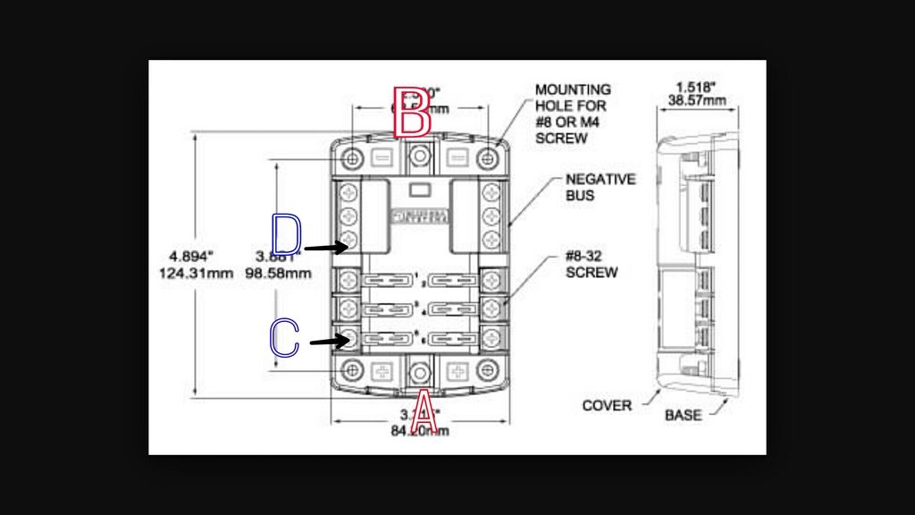
If it's option one , I am guessing you take the negative and positive outputs ( to a device) and put them into the corresponding positive  red "A" and negative red "B" of the fuse block ??

Question 3

If, for example, I am connecting the positive and negative wire from my Fantastic Fan, I assume the positive wire goes to blue "C" and the corresponding negative wire goes to blue "D"???

blue%20sea%201_zpsxsu3xhom.jpg
 
Panels>controller>battery>fuse block>devices

If by fuse block you mean the electrical distribution panel
 
The electrical block takes the positive wire from the battery and connects it to a distribution bus. From that bus, different circuits - each with a fuse - split off to be used for various devices. The negative wires from each device are connected and run to the negative side of the battery. In my camper, the negative wires are connected outside of the panel.

Is this what your asking?
 
image.jpg


Quick sketch:

Each line coming from the panel has its own blade fuse...

And the 'device' can actually be a circuit with several devices - such as house lights - in the circuit.
 

Attachments

  • image.jpg
    image.jpg
    343.8 KB
It's late, I'm tired, and that may not be what you're asking lol...
 
One Awesome Inch said:

Seraphim is basically correct.  Let me summarize:

Solar panel to charge controller.  Charge controller to house battery.  Separate inline fuses in the hot wires between the solar panel and charge controller and charge controller and house battery.  Wires from the house battery to the fuse block pictured above.  Hot wire to "A".  Ground wire to "B".  If there is any real distance between the House Battery and the fuse block, there should be an inline fuse in the hot wire to "A" to protect THAT line.  Hot wire from "C" to your Fantastic Fan.  Ground wire from your Fantastic Fan back to "D".  Fuses in the fuse block need to be sized to protect whatever they are powering.  Fuse in the wire to "A" needs to be big enough to provide all the power the fuse block needs. 

I think the confusion comes from you thinking you could use fuses in the fuse block to protect the solar panel and charge controller.  Not really practical.  They need to separate inline fuses.

Your house battery will end up with TWO wires on each post.  One from the charge controller and one to the fuse block on the hot post, and ground wires from the charge controller and fuse block on the ground post.  Might be a third wire on the ground post if you ground your house battery to the chassis.  And if you are trying to use your alternator as well as the solar, that wire will end up being the third wire on your hot post.  It too needs protection with inline fuses, one close to the house battery and one out under the hood where it ties into the charging system.

Regards
John
 
Thanks guys. I'll think over all that was posted. I might need clarification once I start putting the stuff together. Looks like I'm going to need more heavy wire for the battery connections.
 
Seraphim that diagram you drew is very helpful, thank you.

Any idea what value those inline fuses should be?
 
One Awesome Inch said:
Any idea what value those inline fuses should be?

You still going with one 100 watt panel?  If so, 10 amp would be alright for the input to the controller.  You could use a 10 for the output, too, probably, but it wouldn't hurt anything to use a 15 amp there either.  The fuse for the hot wire to the fuse block needs to carry all the current the block is going to distribute, so you size it to protect the wire itself.  12 gauge wire should be fused at 20 amps, 10 gauge wire at 30 amps.  If you needed more power than that, you'd have to go to a bigger power (and ground) wire, maybe 8 gauge or even 6 or 4 and fuse appropriately - 50, 80 and 120 amp fuses, if memory serves.

Regards
John
 
Yeah a single 100w panel is what I have. Thanks for the info John, very helpful.
 
When I drill a hole into the roof for the solar panel wires, can I use weather resistant caulking or do I have to buy Dicor? Dicor is hard for me to get where I live... and I am sure the RV shops are going to charge $20 a tube if not more.
 
One Awesome Inch said:
When I drill a hole into the roof for the solar panel wires, can I use weather resistant caulking or do I have to buy Dicor? Dicor is hard for me to get where I live... and I am sure the RV shops are going to charge $20 a tube if not more.

I haven't done my own install yet.  When I do, I'm planning on using these: http://www.amazon.com/Ancor-765002-...&sr=8-1&keywords=waterproof+wire+pass+through

I thought we did a whole thread on this a while back . . .

Here you go: https://vanlivingforum.com/Thread-solar-panel-wires-through-the-roof

Regards
John
 
Top