But where does the starter solenoid fit???

Van Living Forum

Help Support Van Living Forum:

This site may earn a commission from merchant affiliate links, including eBay, Amazon, and others.

Paisley777

Well-known member
Joined
Dec 5, 2014
Messages
159
Reaction score
0
Hello,

I have a doner van that was set up with a house batter, isolator, and fuses.  As I don't automatically trust work done by others (been burned way too many times), so I wanted to look at the installation instructions (group 1).  Here is what I find:

http://www.allbatterysalesandservice.com/graphics/INSTRUCTION_SUREPOWER_Isolators.pdf

Problem is, in all the schematics I find to add a house battery, I never see the starter solenoid listed.  They just show the alt to the isolater then to the 2 batteries.  So, where does the starter solenoid fit in?   :huh:

Thanks,
Paisley
79 Ford E150
 
Paisley777 said:
Hello,

I have a doner van that was set up with a house batter, isolator, and fuses.  As I don't automatically trust work done by others (been burned way too many times), so I wanted to look at the installation instructions (group 1).  Here is what I find:

http://www.allbatterysalesandservice.com/graphics/INSTRUCTION_SUREPOWER_Isolators.pdf

Problem is, in all the schematics I find to add a house battery, I never see the starter solenoid listed.  They just show the alt to the isolater then to the 2 batteries.  So, where does the starter solenoid fit in?   :huh:

Thanks,
Paisley
79 Ford E150

I checked out the instructions that you linked.  That is a diode based battery isolator that will have about 0.6 voltage drop.  The voltage drop makes it a great way to kill batteries by not charging them properly. 

A constant duty solenoid would be a far better choice.  The voltage drop would be nearly zero.

I like the Cole Hersee - Smart Battery Isolators.  They are solenoid based.  The fact that they will actually do some smart things like not starting to charge your house battery until your starting battery is at or above 13.2v for two minutes.  This allows your alternator to cool off from recharging your starting battery before beginning to recharge your house battery.  

From my point of view the starter solenoid is not really an issue in this case of using the alternator to recharge a house battery.
 
Damn. Is there an option that isn't $100? That is quite a chunk of my monthly pay. :/
I'm trying to use what I can salvage as much as possible.
 
Remember, you do NOT want a starter solenoid. it is the opposite of a continuous duty solenoid. How long does your starter run for? Seconds or minutes so it is NOT intended to have power run through it continuously like a continuous duty solenoid is,
Bob.
 
akrvbob said:
Remember, you do NOT want a starter solenoid. it is the opposite of a continuous duty solenoid. How long does your starter run for? Seconds or minutes so it is  NOT intended to have power run through it continuously like a continuous duty solenoid is,
Bob.

I have been a little fuzzy headed lately, but my thought was that the starter solenoid goes on the starter, not in the charging system.   :idea:
 
GotSmart said:
I have been a little fuzzy headed lately, but my thought was that the starter solenoid goes on the starter, not in the charging system.   :idea:

Mine is attached to the positive of the main battery.
 
akrvbob said:
Remember, you do NOT want a starter solenoid. it is the opposite of a continuous duty solenoid. How long does your starter run for? Seconds or minutes so it is  NOT intended to have power run through it continuously like a continuous duty solenoid is,
Bob.

Ok.... More confused.  (not hard to do.   :blush:  )

Now I have a standard van set up.  Alternator, regulator, starter solenoid/relay/patato/patahto to battery.  (basically) Like the pic. attached.

So, if I add in the 2nd battery and an isolator... where does that original starter relay & regulator fit in the whole set up?  I can't imagine it gets completely bypassed.  That was the original question since the diagrams I found never showed the original starting circuit involved at all, just 2 bat, isolator, & alt.  Do they just not bother showing the original set up and you piggy back the existing cabling? (pic 2)

Thanks in advance for helping with the newb questions.
 

Attachments

  • Screen Shot 05-22-16 at 10.23 AM.PNG
    Screen Shot 05-22-16 at 10.23 AM.PNG
    206.5 KB
  • set up 2.jpg
    set up 2.jpg
    309.8 KB
Are you planning to use a battery isolator, or a continuous duty solenoid?

I'm going to assume that you are going to use a continuous duty solenoid, as that is the better way to do it.

First, understand that that is a SECOND solenoid used in addition to the starter solenoid.

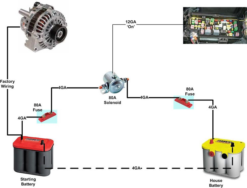
In your first picture, run a second heavy wire from the hot post of the original (engine) battery to one side of the continuous duty solenoid.  Run a second heavy wire from the other side of the CD Solenoid back to the second (house) battery.  You will also need to run a thin hot wire from the ignition switch, or some other circuit that is only hot when the engine is running to one of the small terminals on the CD solenoid.  The other small terminal goes to ground.

Understand also that the second (house) battery must be grounded to the same ground the first (engine) battery is grounded to, or this won't work.

Finally, you will need one fuse on the CD solenoid and an identical fuse on the house battery.  Since there are two batteries, and current can flow in either direction, you need two fuses to protect the wire between the two batteries from being shorted out.
 
Paisley777 said:
Ok.... More confused.  (not hard to do.   :blush:  )

Now I have a standard van set up.  Alternator, regulator, starter solenoid/relay/patato/patahto to battery.  (basically) Like the pic. attached.

So, if I add in the 2nd battery and an isolator... where does that original starter relay & regulator fit in the whole set up?  I can't imagine it gets completely bypassed.  That was the original question since the diagrams I found never showed the original starting circuit involved at all, just 2 bat, isolator, & alt.  Do they just not bother showing the original set up and you piggy back the existing cabling? (pic 2)

Thanks in advance for helping with the newb questions.

The the starting system and charging systems are two original equipment, separate systems that both connect to the same starting battery.  What we are trying to help with here is adding another system to charge a house battery that will also be connected to the same starting battery that sits in it's stock location under the hood of the van.  But, other than being connected to the same starting battery under the hood, it is a separate system.  So no reason to be concerned about the stock starting solenoid in the context of installing a system to charge a house battery.
 
Something that has not been stressed enough. The two 80 amp fuses that are shown in the diagram that Sternwake linked should be no farther than 7 inches of 4 gauge wire from either positive battery terminal on the respective battery that they are protecting. The closer the better.

In that linked page with the diagram it gave three choices on the continuous duty solenoid.  The "good" choice made in the USA made Cole-Hersee solenoid is the way to go.  The cost difference is truly minimal.
 
Paisley777 said:
Ok.... More confused.  (not hard to do.   :blush:  )

Now I have a standard van set up.  Alternator, regulator, starter solenoid/relay/patato/patahto to battery.  (basically) Like the pic. attached.

So, if I add in the 2nd battery and an isolator... where does that original starter relay & regulator fit in the whole set up?  I can't imagine it gets completely bypassed.  That was the original question since the diagrams I found never showed the original starting circuit involved at all, just 2 bat, isolator, & alt.  Do they just not bother showing the original set up and you piggy back the existing cabling? (pic 2)

Thanks in advance for helping with the newb questions.

Alternator;  generates the power from the mechanical action of the engine.  Usually by belts off of rotating pulleys. 

Battery;  Stores the power generated by the alternator

Regulator;  takes power from various sources, and alters them to one specific (or several depending on the design) voltage. 

Solenoid;  Starter, takes battery power and gives it a boost to spin the starter.  This is designed for short term useage.  

Solenoid;  Continuous Duty, takes power and relays it to a specific place.  For your useage, a set of house storage batteries.

On my house battery system, I pull the power direct off of the Alternator (1) to a fuse. (2) Then it goes to the Continuous duty Solenoid (3) and then to a second fuse, (4) then the house batteries. (5)

I have a switch that allows the CD Solenoid to be operating or not.
 
Paisley777 said:
Damn.  Is there an option that isn't $100?  That is quite a chunk of my monthly pay.  :/
I'm trying to use what I can salvage as much as possible.

When I first started out I just used a $8 battery cable switch  ,  switched everything manually .
 
Yes, in this instance of wiring up a house battery, consider the alternator charging circuit completely separate.  Forget the starter solenoid completely for now.


Simple-dual-battery-setup-L.jpg


Regarding performance of this house battery charging system, its efficacy in charging batteries to as high a state of charge as possible, as quick as possible, the diagram above is lacking.

Where it says 'factory wiring'  this is an electrical bottleneck that limits current flow to a house battery depleted below 80% charged.  Most vehicles factory alternator circuit is sized only large enough 'just to get by' type of logic. as the manufacturer's didn't say one day, 

"Hey, incase somebody in 20 years wants to convert this into a campervan and cycle additional batteries deeply, lets make the alternator circuit wire 2awg and use a really fat ground wire to the engine too!!"

No the conversation went more like.  "What is the absolute minimum thickness cable can we get away with?  
Answer "8awg"
---  Sure we can't use 10? 
 "no 8awg  is in the very edge of powering all vehicle loads and should be able to keep a nearly fully charged starting battery, nearly fully charged.

Sigh, well use 8awg then, but we will have to cut corners elsewhere.


So, refer back to that diagram above and see the (+)  factory wiring goes from alternator to engine battery, then to solenoid?

Bypass it.  Hook solenoid directly to alternator(+)  instead of engine battery (+).

4 awg at alternator---> 80 amp fuse-> 4awg----------------> 120 amp CDsolenoid------------------>-80 amp fuse--->house battery(+).


That is the (+) side of the circuit

Regarding the return ground path....
Also one can ground  house battery directly to nearest frame, OR directly to engine battery, OR directly to alternator mounting bolt or a (-) Alt stud if one exists on the alternator.  If one grounds directly to frame nearby house battery, then they should also ground the alternator to the frame, or increase the thickness of the wire from engine battery to engine block, for better performance, or just add another in parallel.

This wiring route will significantly increase charge rate into depleted battery upto 80% charged, but not really help speed things up from 80 to 100% which is basically 4 hours minimum, no matter the charging source.
  It depends on the voltage your vehicle's voltage regulator allows.

But the VR will hopefully see the increased alternator field current required to achieve maximum voltage, and allow it to be held longer.  Vehicles VR's are wacky things, also not designed to consider recharging additional batteries.  Better vehicle voltage regulation can be accomplished but is a different topic.

This  upgraded alternator charge circuit will also increase the load on the alternator, heating it more, shortening its lifespan to some unknown degree.

The danger lies mostly with vehicle alternators which can produce high amperage when hot and at idle speeds, and the user decides to idle to recharge a very hungry depleted battery which can ask for 60+ amps.
  The slow spinning alternator fan cannot remove enough heat from it, and combine this with baking under the hood, can easily allow the alternator to exceed 220F and  spend too much time in this temperature range/ danger zone.

When moving the higher rpms and air movement underhood significantly decreases alternator temperature, at least on my Van.  Especially highway speeds. it can be maxed out and only 110F at 65mph, but pull off the freeway and idle at a traffic light and it can spike to 160F in a minute.  Still collecting more data on this.

So One 'could' intentionally reduce the load on the alternator by using thinner cabling and sacrifice better battery charging.  if one's alternator is a huge PITA and expense to replace, then it makes no sense to overtax it trying to extend battery life, but making sure one has enough recharge occurring to power their Cpap overnight.

So there are performance options to consider, and the capability of any vehicle's charging system can be vastly different that of another brand/year so blanket statements are best avoided, but at the same time there are generally truths in this arena, with exceptions.

One thing also not yet mentioned is the rating of the vehicles alternator.  This rating is earned in a laboratory with a cold alternator spinning fast and huge loads asking for everything the alternator can make over very thick copper cabling.

The '140 amp' rating means that is the absolute maximum it can ever hope to employ in ideal conditions, and only briefly.

What a higher amp rating really means to a vandweller is that the alternator is more likely to be able to shed the excess heat it will generate when asked to work really hard charging a depleted battery at its limits of amperage acceptance at the voltage allowed by the vehicles voltage regulator.

A higher rated alternator 'might' not be able to product any more amperage at idle speeds than its lower rated counterpart.  I could pull up some graphs from Balmar showibng an example or two, but I've spent too much time writing this as is and will click submit no
 
One comment on the diagram Sternwake posted.  The solenoid shown only has one small stud hooked up to a "12 gauge on".  That solenoid needs to be grounded to the frame via it's mounting bolts in order to work.  Some solenoids have TWO small studs.  Their mounting bases are insulated.  They need one hot wire and the other one needs a wire run to ground.
 
Wow! Thanks so much everyone! I am going to read and study these while I wait for the CD solenoid to be delivered. :)
 

Latest posts

Top